

Vario Chinook on the Table
 Michael K.
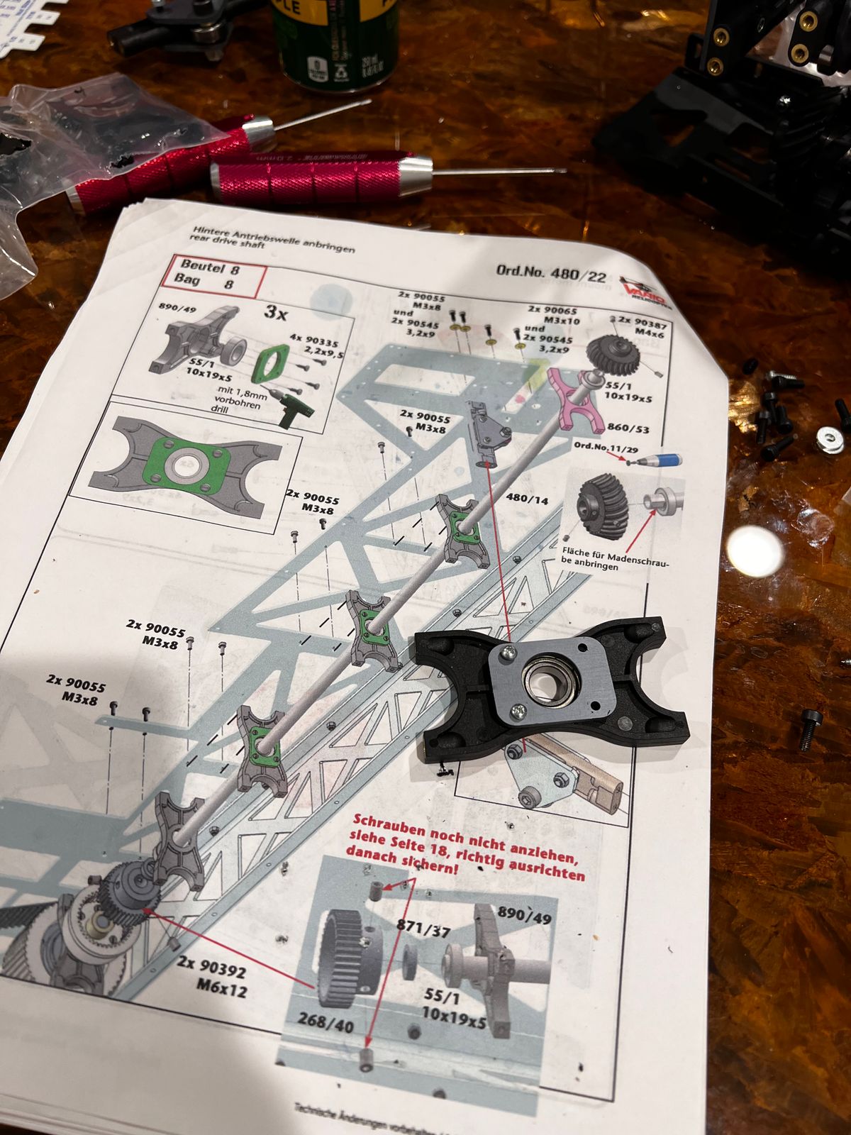
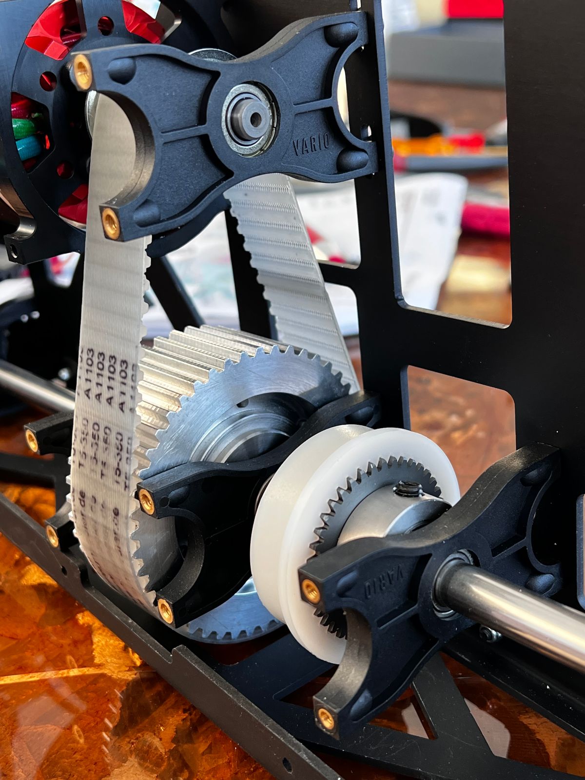
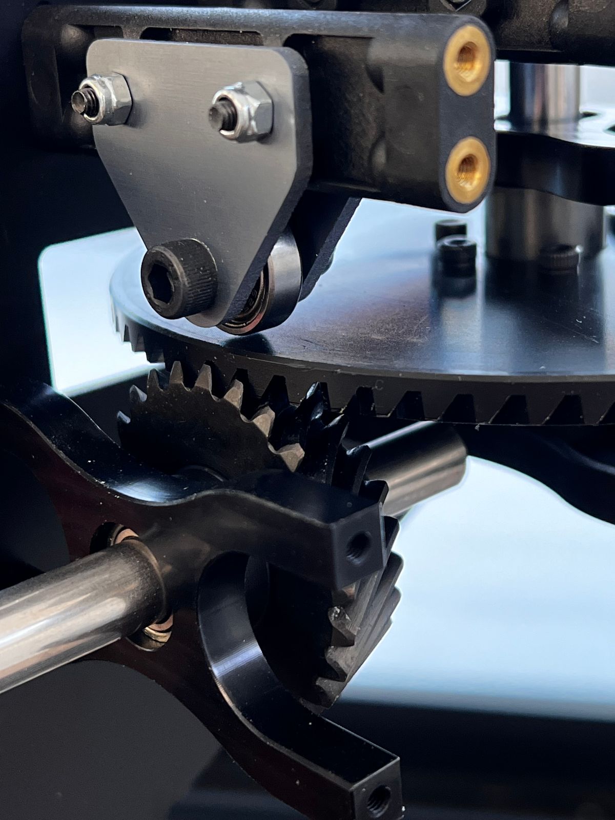
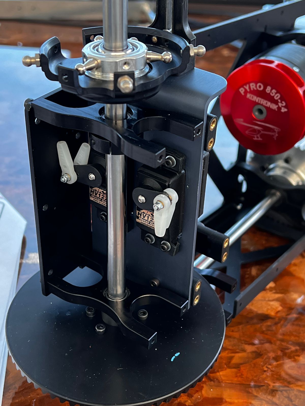
Mechanically Inclined
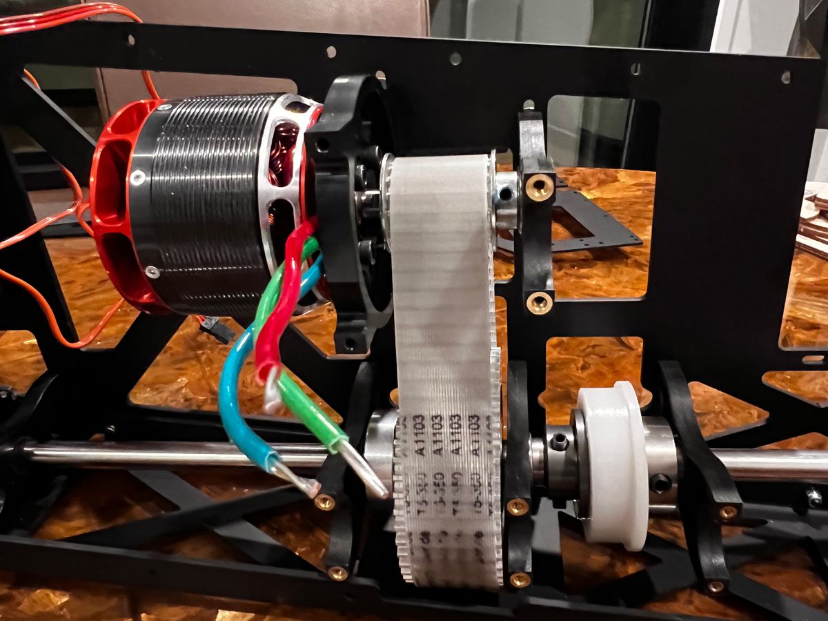
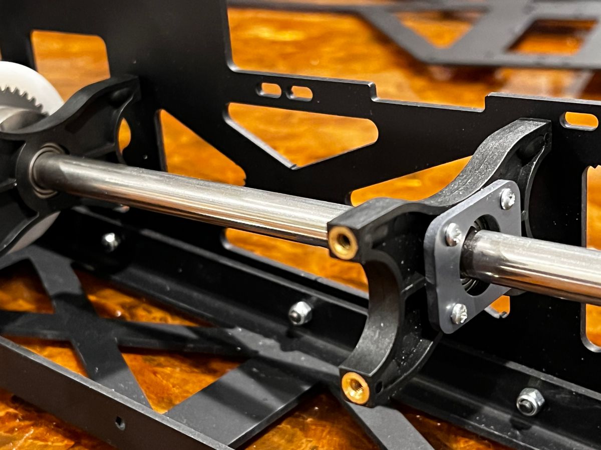
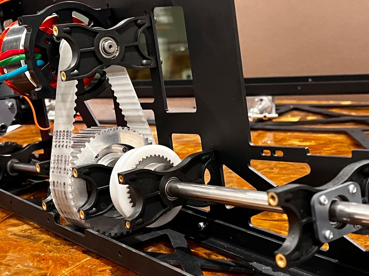
I didn’t start at the beginning but still thought it would be fun to share my progress on the Vario Chinook. The mechanics are FUN! The parts are intelligently packaged and the instructions are a pleasant departure from some older Vario models I’ve had.
I plan to build and fly the mechanics separately before even attempting the fuse.
You can order the Chinook from Mark Smith of HeliWorkshop.com! Mark knows his stuff and offers help from his decades of experience.
Shafts and Gears
I probably sound like I’m building my first RC heli kit but it’s hard not to gush a little bit when describing the construction of the Vario Chinook mechanics.
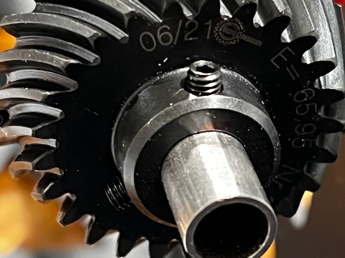
Vario’s drive system for this tandem looks solid with a stout main drive shaft that drives two disk gears with spiral teeth. The pushrods for each swashplate are all angled at one end because they must pass through a narrow aperture from the servos and then wing out to meet the ball links on the swash. The servos each drive two pushrods with an ingenious double ball link on each arm.
Once I get the left frame on, I’ll begin the critical stems of ensuring that each swash is oriented 90 degrees from its respective shaft. The front shaft tilts forward so I’ll shim up the front of the fuselage to calibrate the front rotor.
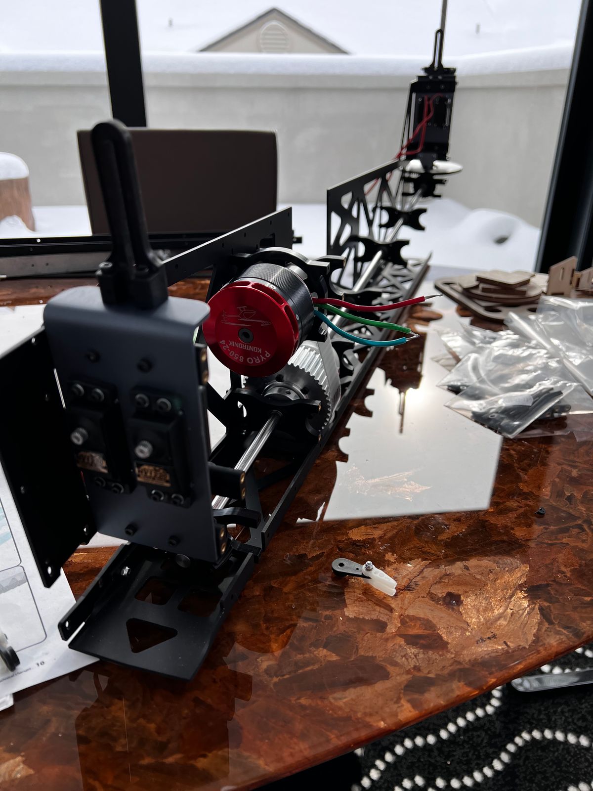
Gyro, ESC & Wiring
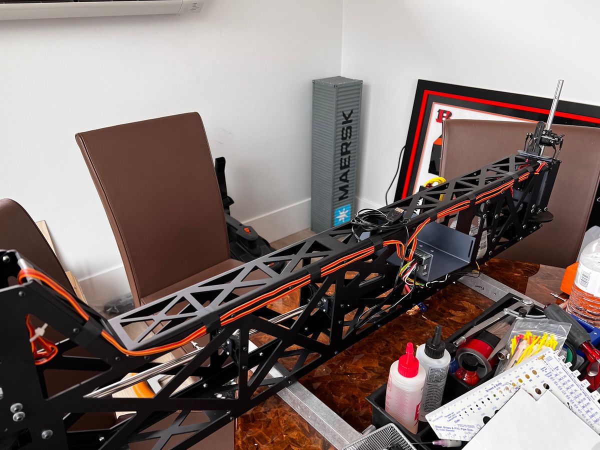
I intend to fly this beast without the fuselage so I will complete the setup of the mechanics only. I mounted the gyro in the center of the mechanics so it should be easy to access with a small servo extension.
I’m still waiting on the rotor heads but I was able to program the ESC and the gyro without them. To fit the mechanics into the fuselage while waiting for the heads, I’ll remove the front shaft and slide the mechs in. Lots of measuring and cutting to go!
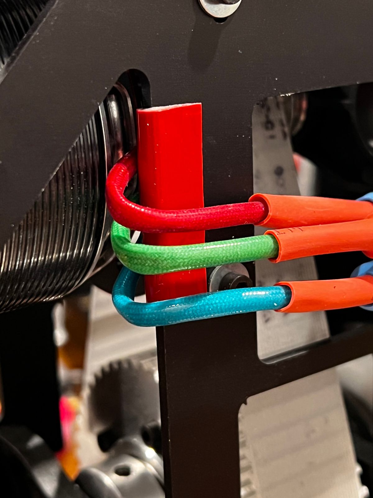
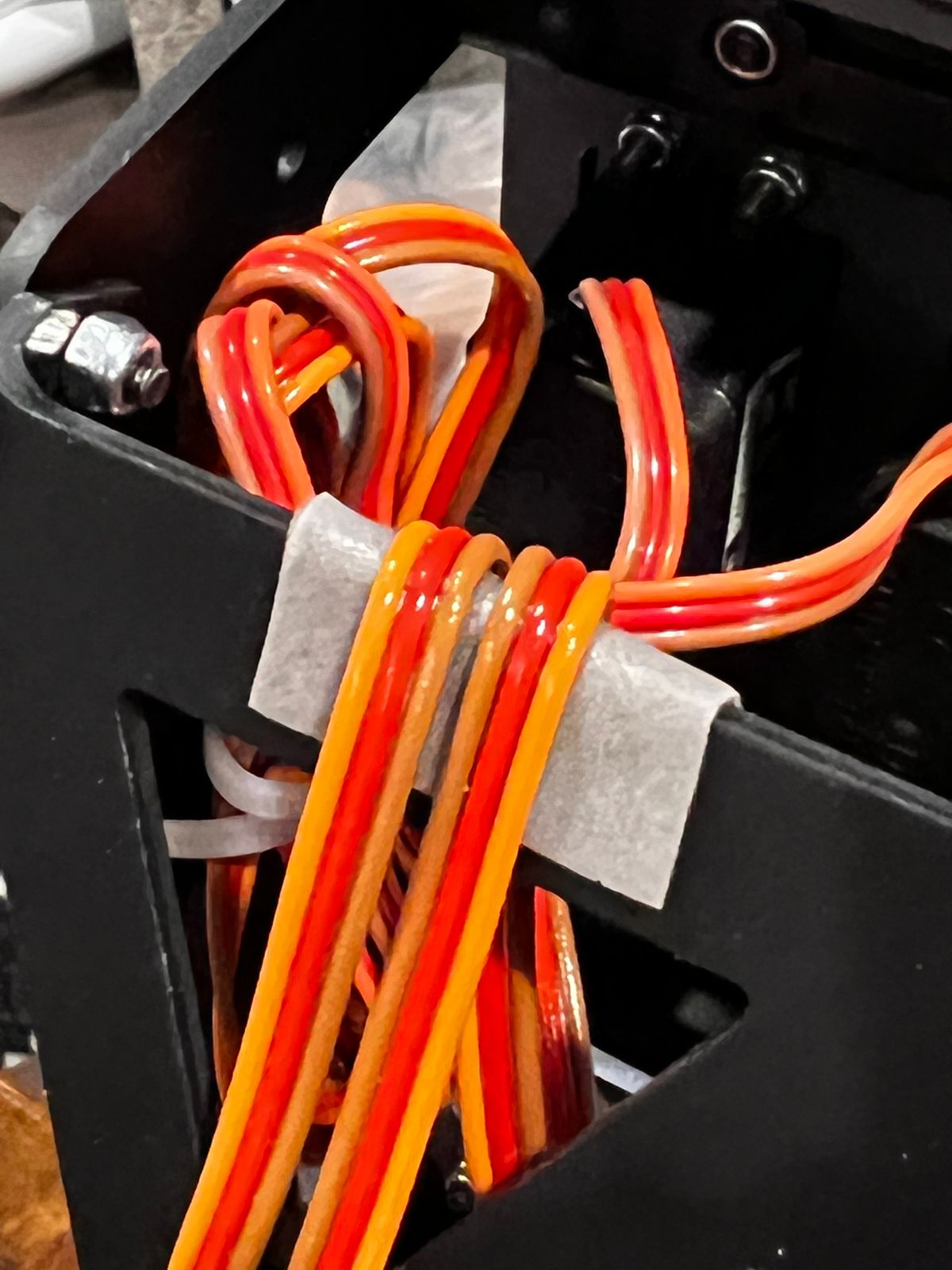
Notice that I applied double sided foam tape where wires could rub against the sharp aluminum edges.
UPDATE: I rotated the Demon 3SX so that it's mounted against the mechanics vs the battery tray. Although the Axon can handle transverse mounting (like I show here), the 3SX cannot. Also, note the location of the gyro in the center of the mechanics. After conferring with Demon and an RC electronics expert, I am comfortable that the proximity of the gyro to the batteries is NOT a potential interference risk.
Fits & Bits
In constructing the Chinook, I've noticed a number of modeling opportunities (and by that I mean opportunities for you to get out your Dremel and sanding boards):
1. Prepare to slide the mechanics in and out of the fuse A LOT! I recommend removing the front pushrods to make the slide easier.
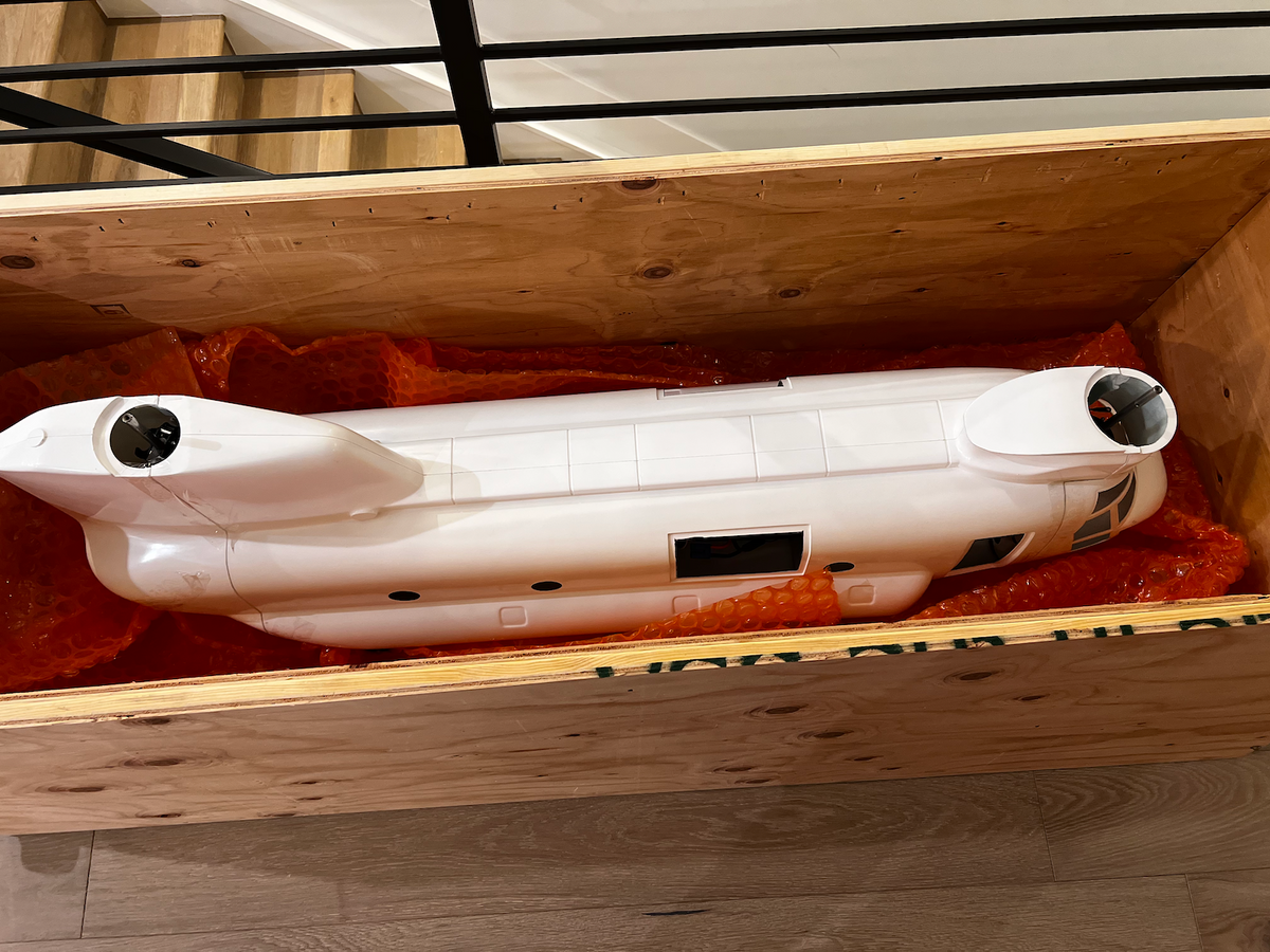
2. Although not specified in the instructions, I recommend removing most of the flange areas on the front and back. As the photo shows below, I left about 1.5" of flange at the top for anchor bolts but otherwise removed the fiberglass to make getting the fuse in and out easier.
3. When testing the fit of the fuse, keep all mounting cleats LOOSE until everything is connected; then you can torque down the bolts.
4. BUY A COMPASS/SCRIBE to make the precise circle cuts in the two top domes. You'll thank me later. Sure, you can trace a cup or some other thing, but the scribe lets you get things precise and score the fiberglass for easier cutting.
5. I replaced the included wheels (hard foam) with DuBro 2" Low Bounce Treaded Tires. They look great; I'm not sure whether they will develop flat spots. 😬
6. For drilling the circular openings for the landing gear legs, I recommend a step bit! makes for easy work.
I've been in the hobby for 50 years. This was my FIRST time attempting a build on a Vario. Cutting and sanding fiberglass, gluing formers and doing what I call "artwork" is something I shied away from until now! It is fun! I've always enjoyed mechanics, fuel systems, electronics and all the other shiznizzle but the glasswork was interesting. I have shipped my Chinook off to Tyler Gray Models for the beauty work. THAT, I'll never do!
Finished Model
It's been awhile since my last chapter! I completed the mechanics and went to test fly them. A couple of things went seriously awry:
1. The pitch recommendations in the instructions (-4 to +12) are a bit too much at the bottom in my opinion. I had -4 set and had forgotten to put in expo on my initial flight. After rearing back like an angry thoroughbred, I dropped collective too quickly and the front rotor crushed the top and side aluminum frames. It also screwed up the head so I ordered replacement parts.
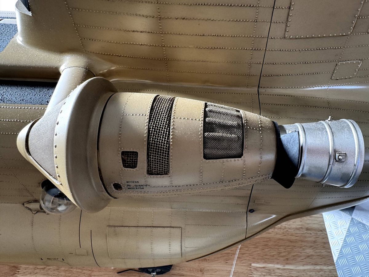
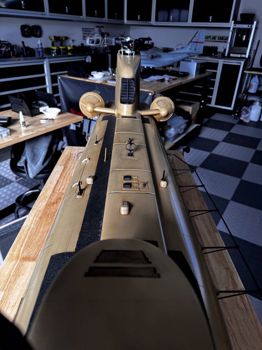
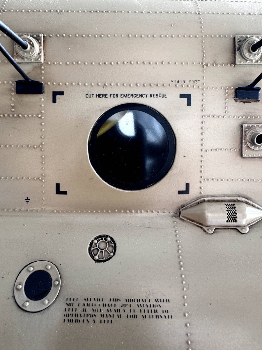
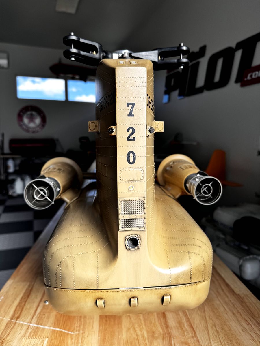
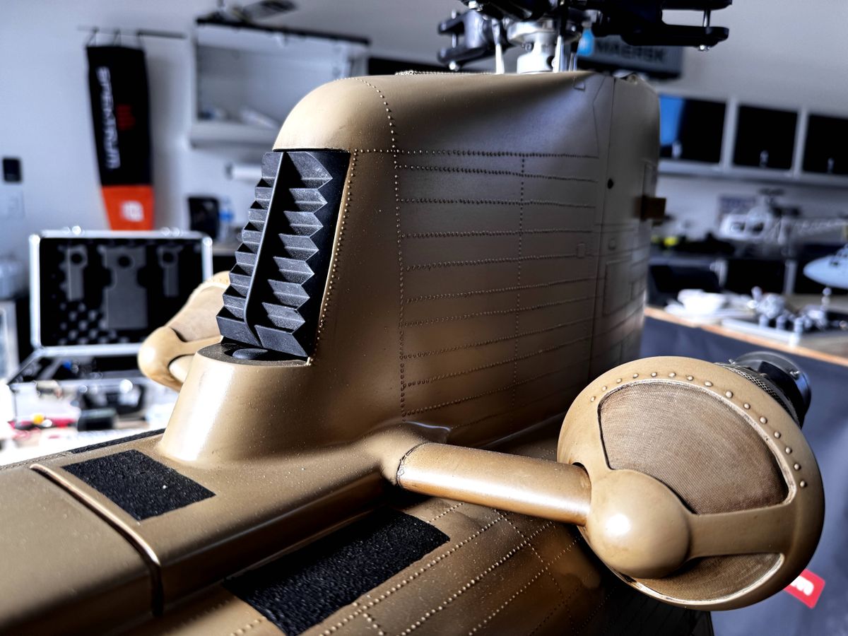
2. Meanwhile, Tyler Gray was working on the paint, fiberglass, fittings, lights, sound and scale details.
3. I receive my parts and after putting off the inevitable deconstruction-reconstruction process, I did it. I spent several hours dialing in the blade pitch and swapped the Vario pushrods for Secraft turnbuckles. This allowed me to get within a 1/10th of a degree on each blade.
4. The maiden was truly uneventful. She lifted straight up and hovered perfectly. I did not fly the mechanics because I was certain I would lose orientation and destroy it. Now back to the shop for final fitment.
5. Getting everything together is a bit of an ordeal. You have to unbolt the entire front shaft stack in order to slide the mechanics into the fuse. You also have to remove the landing assemblies. Arranging the sound board, light board, receiver and batteries (for sound and lights) is fun, but painstaking. In addition, I burned out my landing lights so I needed to install new ones.
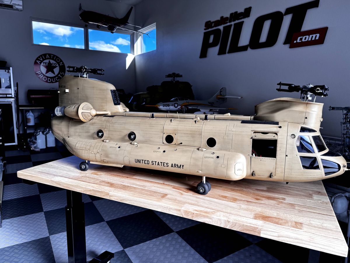
6. Once complete, the model is ready to go! I left off the spinning rotor caps for now because the turnbuckles are a bit wider than the apertures for them and I have no patience for disassembling the heads.
HOW YOU LIKE ME NOW?!
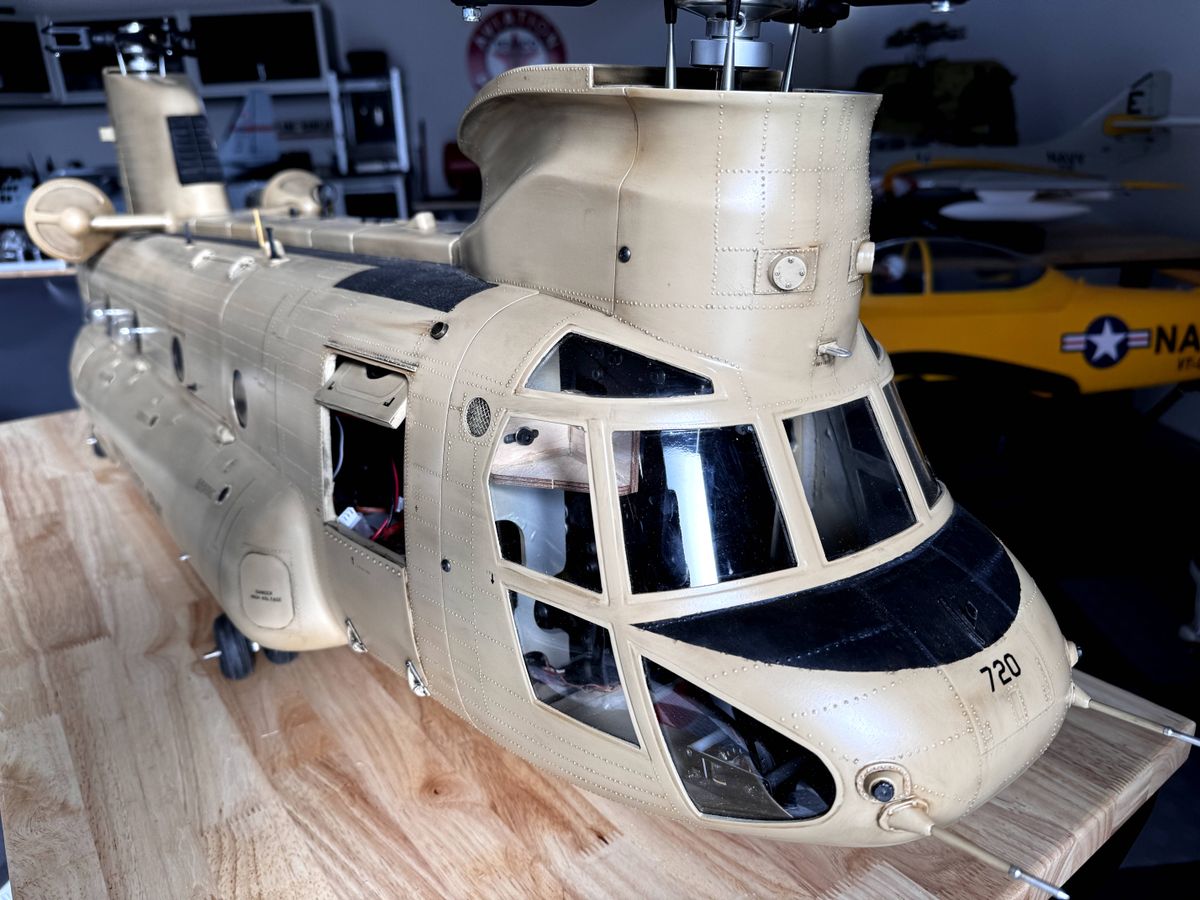
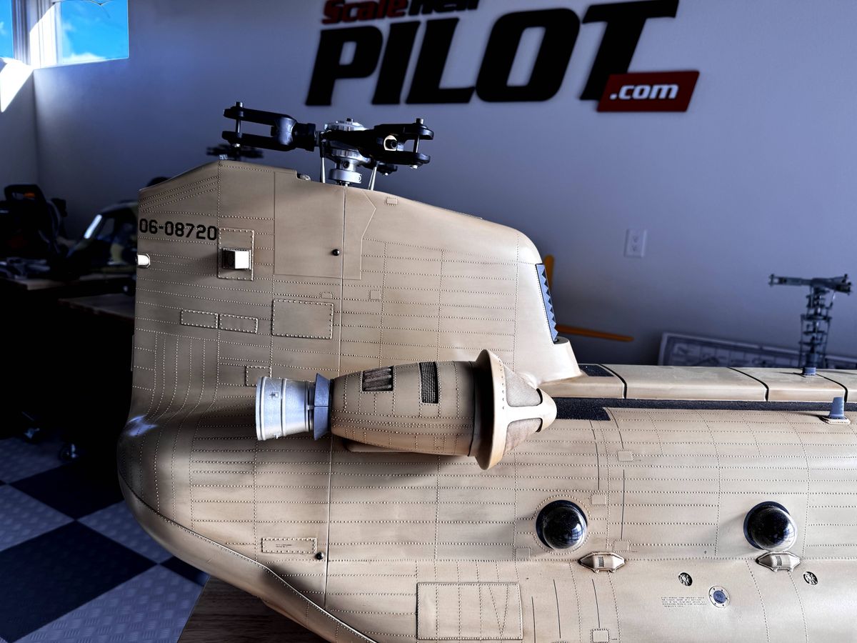
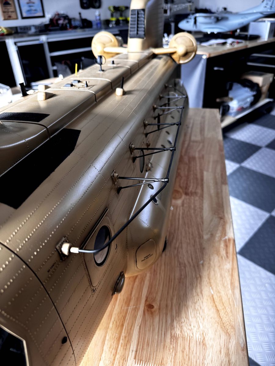
Possible Head Issue
This past weekend, I took the Chinook out to the field for its first fully clothed ascent. After an initial 30-second hover, I went to take off again when, at full rotor RPM, the front rotor SEPARATED from the main shaft. On its way off the model, the front rotor collided with the rear and made straw out of my blades, but incredibly there was no other damage to the model.
[SINCE I FIRST POSTED THIS, I LEARNED THAT MY INCIDENT IS DIFFERENT FROM WHAT OTHER PILOTS HAVE EXPERIENCED]
I have written to Vario about this incident. Kirsten has responded and I'm in conversations with their team pilots to determine the cause. I did use thread locker but I cannot determine why this happened or whether or not it will happen again. Sandy Jaffe (team pilot) has 300+ flights on his model with no incidents.
More to come...
45 Comments
Looking good Michael…
for some reason this one comes back as invalid source
What comes back as an invalid sources where?
When I klick on the picture it comes back as the "invalid source"
It works now! Thanks for the heads up!
awesome thanks for the fast fix
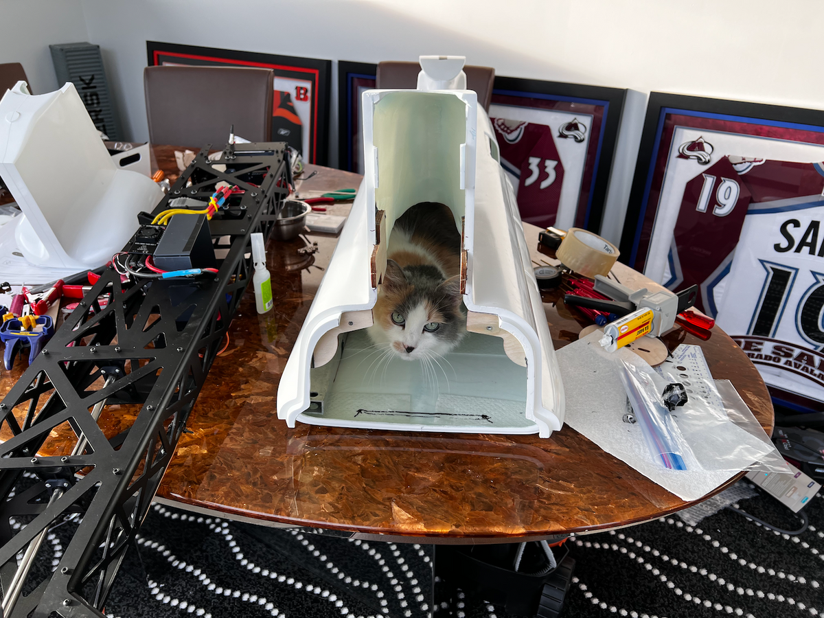
Love the crew chief inspecting the work...
Tyler did a great job with the fuselage....
Big time!!
Beautiful, just need to get mine done, Tyler does some amazing work.
How do you test fly the mechanics? Have you made any landing gear for the mech? Thanks.
To test fly, you simply attach the aluminum mounts to the mechs and add the wheels.
Hi Michael. You will love flying this model, it is really stable and looks very realistic in the air with lots of presence. I have flown mine a lot, I have lost count of the number of packs through it now but I feel really comfortable with it. Probably around 60 or 70 now. Over this winter I have given it an "annual inspection" as just taking off the back and front shells doesn't reveal everything. I found that one of the bearing blocks supporting the layshaft had moved a little allowing a very small amount of end float so I adjusted that. There was no chafing of cables or belt and everything else held tight. The gears are as new. The new season will start here in the UK in about 4 weeks.
I am not using the Vario heads. Instead I have modified Align Trex 700 tri blade heads so the blades flap. They can be bought from Midland Helicopters now as they asked me to machine them for them to sell.
https://modelhelicopters.co.uk/products/scoobydoo-rotorheads-f-vari...
There is a comprehensive build thread on mine at the address below. You will need to register to see the many pictures I took along the way. The build had its ups and downs so is well worth a read. I know you asked me to copy it over to scalehelipilot.com but it was just too much work as it is 44 pages long and would lose the valuable interaction with the thread members. It can be seen here
https://www.scalerchelis.com/phpBB2/viewtopic.php?t=19890
I wish you the best of luck with your maiden. It is quite easy to see with the fuselage on but really difficult when it's in the nude!! I covered all that in the build thread.
Kindest regards Jonathan
Thanks for the great information! I cannot access ScaleRC because I believe their “human test” to reset password is broken or my IP is blocked. I am interested in the head modification, however. Do you use the plastic domes?
Yes I use the plastic printed rain domes. The position of the mechanics has to be very precise to stop them fouling on the fuselage, I covered that in the thread. As the fuselage moulding has a slight distortion in it making the rear tower lean slightly the challenge is even greater. The mechanics have to be used to straighten this out so the rain domes fit. If you contact Mike Spinner he should be able to sort you out a login or point you to someone else who can. The modified Align heads are available off the shelf if you want them from Midland Helicopters. They can sell them to you without the 20% VAT that we pay here in the UK so cheaper than getting them from me direct.
https://modelhelicopters.co.uk/products/scoobydoo-rotorheads-f-vari...
Hi Michael, u need the -4 collective when you fly faster around. and i think there is no expo need when the settings are correct.
Regards Stefan
Interesting. I will slowly expand the range if needed but I fly at 6,000 feet so my -2 may work fine.
Have have 2 stock heads for sale if anyone needs some
Hey Charlie, please post those in the market area of the site!
Will do
Nice…Really Nice…Congratulations!
Masterpiece - looking forward to seeing it in action
If the weather holds this weekend I’ll be flying at Chatfield!
Nice work, like you protective wiring style!
Thanks!!
There is an alternative... Jonathan's modified Align heads
That is also an alternative, but ideally, Vario would include the bolts and safety wire in the kit along with A WARNING.
That's nuts!
Really sorry to hear about this incident. Good you were close to the ground. Since others including Vario pilots are experiencing this also, wouldn't the best solution is to have CCW threads? I wonder if their new large CH47 has the same design? I really love this bird as I flew in it many times in 1968 when I was in Nam as well as the Huey. I am really interested in the new larger model but not until this issue is resolved.
The new Chinook has the same design!! As for reverse threading that has the risk of getting messed up by modelers.
Thanks for sharing this information Michael and really nice solution!
Thank Gonzalo 😆
A slight design blooper I’d say
Hi Michael, are you referring to the 90530 M3 lock nuts that got loosen during the flight?
No. I’m referring to the 90145 bolt coming loose. That bolt, alone, holds the head onto the shaft.
I see. Thanks for clarification
Hi Michael, understand that the front rotor is left hand rotation, meaning CCW, if I were to use the reversed threading bolts, should I put it onto the front rotor (replacing 90145)? Thanks.
You would have to rethread the shaft. The capstan bolts and safety wire are better in my mind
What kind of saftety wire I should use? Thanks.
.020 should do it. There shouldn’t be much strain on it. It just needs to keep the bolt from rotating more than a 1/4 turn.
With all due respect, the linkages on my standard Heli's (400-700) have threads CW on one end and CCW on the other. Plus the manuals always state this. I find it difficult to believe that modelers familiar with helis ( and new modelers provided they read the instruction manual) would have any difficulty with this. My concern is that the manufacturer did not catch this and went into production and may have a sizeable inventory they do not want to discard. I wouldn't feel comfortable with this patch fix and it detracts from the scale appearance. That just my two cents worth. Not trying to start a war or create any conflict. Until they correct this issue (for me personally) I will hold off and see what develops for the future concerning this particular issue.
I originally thought the opposite threading was the answer but didn’t think it was a realistic solution because I have too many decades of experience handling software support questions (so I can imagine modelers missing this) and because it would cost Vario (and, in turn, modelers) more to make two sets of shafts/bolts. But perhaps the most compelling reason is that having a bolt going through the top is never as good as a Jesus bolt.
What you say makes some sense; however, the cost of these machines are in the stratosphere already and to do both shafts correctly the first time, wouldn't add that much more cost. If I am going to spend that much money on this machine, I would like it done properly and have peace of mind that the hub is not going to fly off because the threading is done incorrectly on one of the shafts.
I really like what I see on this bird but I personally need to feel comfortable in my mind that an oversight like this might cause unneeded problems down the road.
I became aware of Michael's Chinook issue today, March 19, 2024. As we continue to gather facts and information from Michael and others, we will see where this information leads us. The important FACT for today, and the reason for my post here, is that the image above taken of the REAR rotor head of Gonzalo's Chinook shows a Stainless Steel screw safety wired to the rotor head spindle. As of today, this rotor head has NOT yet flown with this modification. If someone in the USA were to do a search for this this type of drilled "safety screw", at can be found at McMaster Carr. BUT, this screw made from 18-8 stainless steel has LESS THAN 1/2 THE STRENGTH of the provided original alloy M4 socket head cap screw. Please keep this in mind if you are considering a modification like this one on your Chinook. Sandy Jaffe - Vario Team Pilot
I just want to say my modification with the safety wire haven't flown yet and I need to recompute some numbers for the type of screw I'm using. So please don't use this solution until we test and re test.