


Be Unfazed by phasing
When it comes to setting up your swash plate, especially on a multi-blade head, many pilots have a rote understanding of HOW to make the blades pitch at certain points when specific cyclic commands are given, but MOST do not understand WHY the rotor disk works the way it does. Some might suggest that learning the WHY behind phasing is like learning how the touch screen on your vehicle works; no need to learn why the pixels respond to your touch as long as you tap in the right places. Right? Wrong. Understanding HOW phasing works gives you a built-in way to verify your setup and it reduces maiden stress! Besides, most hobbyists who play in this arena pride themselves on learning the why and how behind the do.
In this article, we will first explore WHY the rotor disk behaves in the way it does and then we will look at simple, but bullet-proof, methods to ensure that your phasing is set up correctly.
The Wonderful World of Spinning Disks
Phasing is simply the science of getting the swash plate to input the correct pitch commands at the correct time given a specific cyclic input. If you input right cyclic, you want the helicopter to bank right. Unlike an airplane, however, a spinning rotor disk behaves under a different set of laws; namely those which govern angular momentum.
The laws of angular momentum are a bit strange. We all know that a hockey puck sliding across an ice rink will maintain the same course unless acted on by an outside force, like a stick or dasher board. Easy stuff. A rotating disk, on the other hand, acts differently when you apply a force to change the axis on which it rotates. Spoken in ancient Helicopterish, this means that an upward force at one location on the disk will effectuate the intended change 90 degrees from the initial force. For example, an upward force (higher pitch angle) on the left side of a clockwise rotor disk does NOT cause the rotor disk to tilt to the right in the same way a downward left aileron on a fixed-wing aircraft will cause the aircraft to roll right. Instead, that upward force causes the disk to pitch rearward (back cyclic) because the effect of higher pitch on the left will take place 90 degrees later (at the nose in our example). See Figure 1.
Figure 1
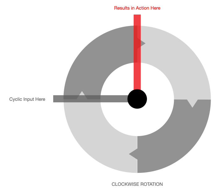
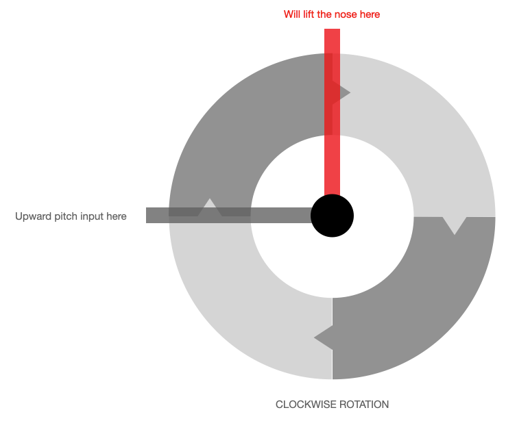
On the same disk, if the upward pitch change occurs at the nose, its effect will not be realized until 90 degrees later, which will result in a left roll motion. Starting to get it?
Precession Precedes All
Why all this spooky behavior happens is the stuff of physics lectures -- so that won't be happening here. Even at the highest levels, engineers and physicists have a handy way to determine how a rotating disk will behave when an external force acts upon it. I mean it when I say "handy."
Hold your right hand in front of you with your thumb up. Slighly uncurl your fingers. The direction of your finger curl represents the direction of the rotor (COUNTERCLOCKWISE in this example) and your thumb represents the torque vector of the axis on which the rotor is spinning. Left undisturbed, the vector will tend to remain in this direction. Here comes the fun part. Imagine standing behind the helicopter and looking down on the rotating disk. Further imagine an upward force (applied torque) applied beneath the disk at the 9 o'clock position. To figure out where the new torque vector points, simply orient your right hand so that the finger curl represents applied rolling motion you just induced with upward force on the disk. If you do this correctly, your thumb will be pointing away from you. Force follows the vector change. Here, the upward force at the 9 o'clock position on the disk will cause momentum to flow from the upward torque vector toward the forward-pointing torque vector resulting in a pitch forward of the the helicopter. Figure 2 illustrates this from the left side of the rotating disk.
Figure 2
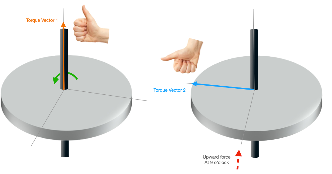
Torque Vector 1: Pointing up
Torque Vector 2: Pointing forward
Angular momentum flows from Vector 1 to Vector 2. So, in the illustration, above, we can see a number of things:
1. Using the right hand rule, the disk rotating in the counterclockwise direction generates a torque vector that points upward from the disk. This is represented by the orange arrow.
2. By applying an upward force at 9 o'clock, we are introducing a rotation of the entire disk/axis assembly in the direction of the force. This is represented by the curled fingers going in the direction of the induced rotation (think right roll).
3. The torque vector generated by the applied force is represented by the blue arrow. It points toward the nose of the helicopter in this example.
4. Momentum will follow Vector 1 toward Vector 2 resulting in a tilt of the entire disk forward -- 90 degrees from the application of force.
5. CHEAT: Imagine applying collective at 9 o'clock and not having it take place until 6 o'clock (counterclockwise rotation). If you applied a lifting force at 6 o'clock, the nose would pitch over, which is exactly what happened here!
If you play around enough with the right hand rule, you will become a master at gyroscopic precession! But do you need these concepts in order to set up your swash? NO!
Enough Physics! How Do I Set Up My Swash?
On any type of head, no matter the blade count, the technique for setting up phasing is roughly the same.
The stars of the show in your head setup are the swashplate and the swash follower. The swashplate (non-rotating part) is responsible for transmitting pilot controls from the servos to the rotating hub that sits atop the non-rotating under-plate and, in turn, to the blades by way of (a) pushrods that run from the servos to the lower part of the swashplate and (b) pitch links that run from the inner rotating part of the swashplate to the blade grips. The swash follower ensures that the pitch links stay in the same orientation relative their respective blade grips. Each grip feathers to alter the pitch of its blade depending upon the cyclic inputs. We should all stand in awe of the genius in the swashplate. The swashplate is stupifyingly simple but astonishingly effective in its execution of the single-most important aspect of helicopter flight; the ability to create inputs that cause the rotor disk to tilt in any direction. The swashplate accomplishes this by changing the pitch of each blade as it passes through each position in its journey around the axis of rotation (e.g. the main shaft). What might seem like a simple tilting of the disk is actually much more impressive than that.
With modern gyro systems, most phasing will come from a combination of mechanical and electronic phasing. Phasing is simply adjusting the swash follower so that stick inputs correspond with increased pitch at certain points in a blade's journy around the main shaft. In our example above, I used a pitch-up at 9 o'clock to generate a disk-forward pitch (nose down). Let's work with that example.
Mechanical Phasing First
Ideally, you will be able to set your pitch link rods in such a manner that they are as close to parallel to one another as possible. There may be some left or right tilt to your rods and that is fine provided that there is not too much stress on the blade grip ball links. Similarly, there may be some outward splay of the rods depending on the design of the head. This is ok too, provided the rods are close to parallel to one another. Your initial stab at this will NOT be your last. Get the initial mechanical setup such that you can conduct the followiing test:
- Take ONE blade and rotate it to the FRONT of the helicopter. Ensure that the blade is perfectly in line with the fuselage.
- Now apply forward and aft cyclic from your transmitter.
- The blade should NOT MOVE.
If the test blade does move, just loosen the follower and rotate it such that the tilt in your lower swash that happens when you apply forward/aft cyclic simply does not push up or down on the corresponding pitch rod. Again, you don't have to be perfect here. If you feel like you are rotating the follower so much that the pitch rods are at concerning angles, back off and tighten the follower at the most comfortable place and then access your gyro software to add DIGITAL PHASING. Digital phasing will alter the motion of the servos driving the lower swash plate to accomplish the same effect as a mechanical rotation of the follower and swash. Make small adjustments in digital phasing until the blade over the nose is not affected by forward/aft cyclic inputs.
Next, rotate that blade to one side of the helicopter and make it exactly perpendicular to the fuselage. This time, run the test with left/right cyclic inputs. The blade should not move. The tests should work on each blade as they are positioned in your test locations. At this point, you can play around with the mechanical vs digital adjustments in order to maximize the integrity of the mechanical setup as discussed above.
Video
This video demonstrates how easy it is to set phasing up (without all the physics)!
Last Pass
Once phasing is complete, cross check your work with what you learned about gyroscopic precession. Flip one of the blades so that it's sticking out perpendicularly to the left (when viewed from behind). Input forward cyclic. If your head rotates clockwise, the forward input should generate NEGATIVE/DECREASED pitch on the test blade. Conversely, if your head rotates counterclockwise, the forward input should generate POSITIVE/INCREASED pitch on the test blade.
You've done it! Dialing in phasing like this will give you confidence that your helicopter will fly smoothly and accurately with respect to your stick movements. Balancing and tracking your blades will also contribute to your happiness, but those topics are beyind the scope of this article!
You are now UNFAZED by PHASING!