

Vario Bell 230 Building
 Danny D.
Building a Vario 800 size Bell 230
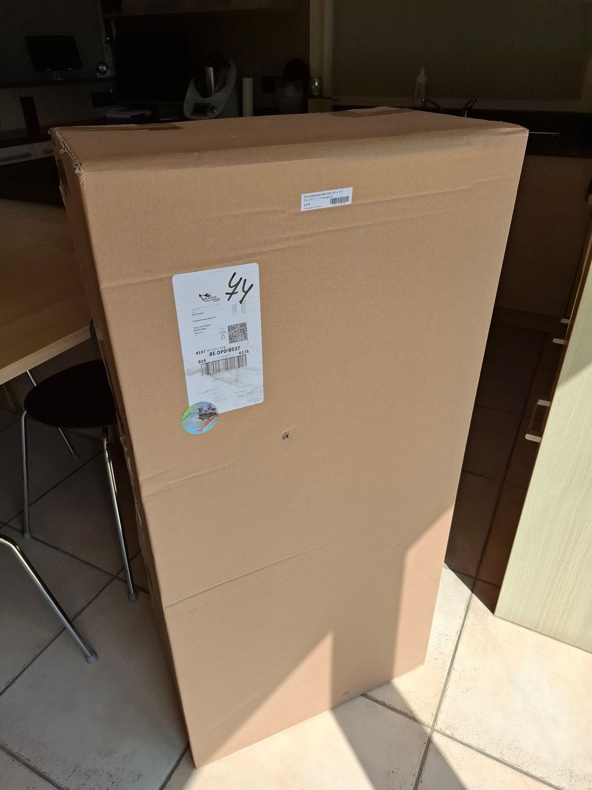
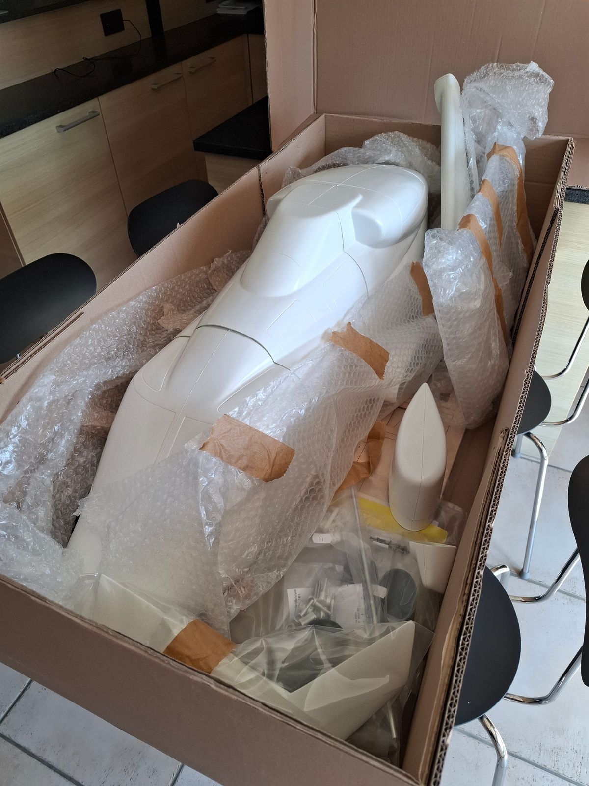
It all starts with a big box and a lot of parts....
No clue of the all the work that is to be done. :-)
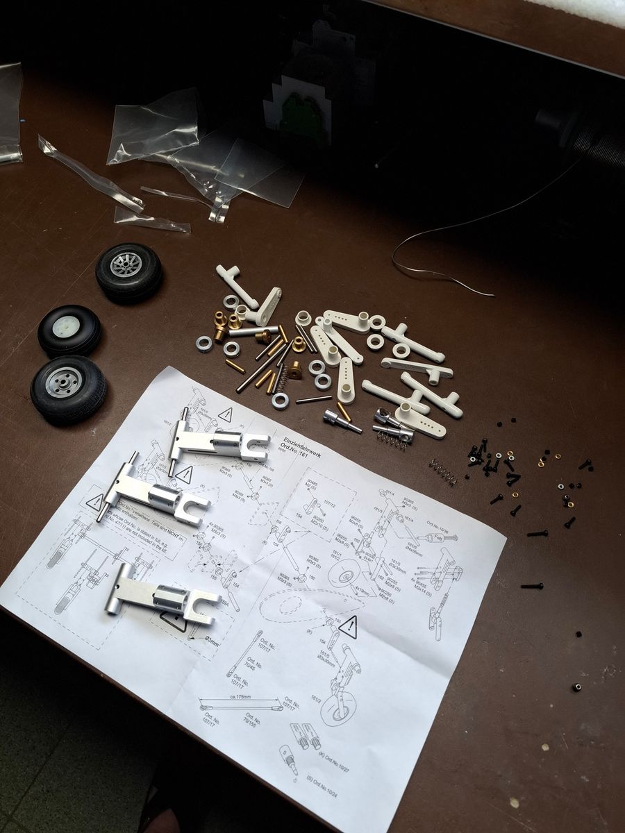
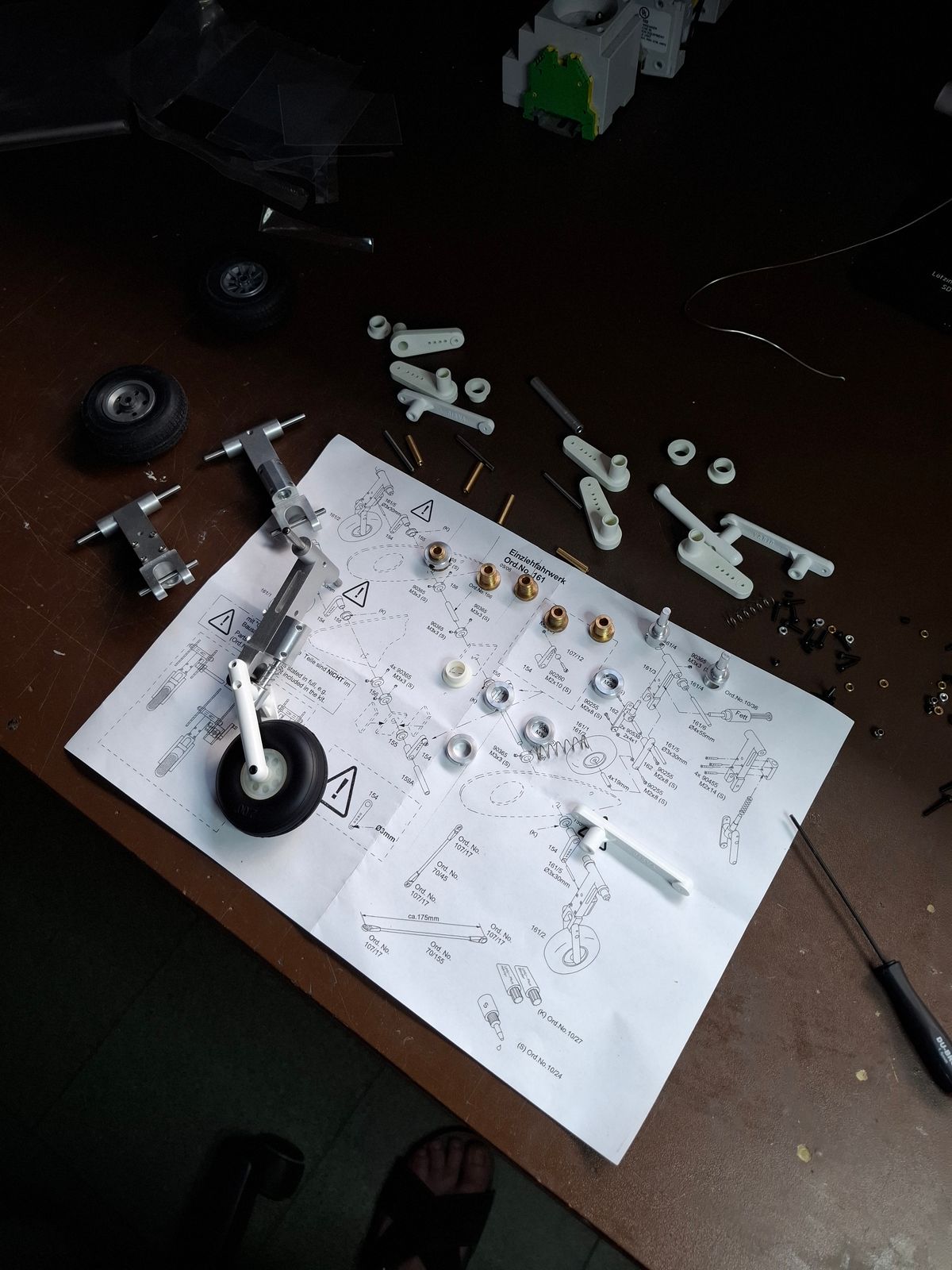
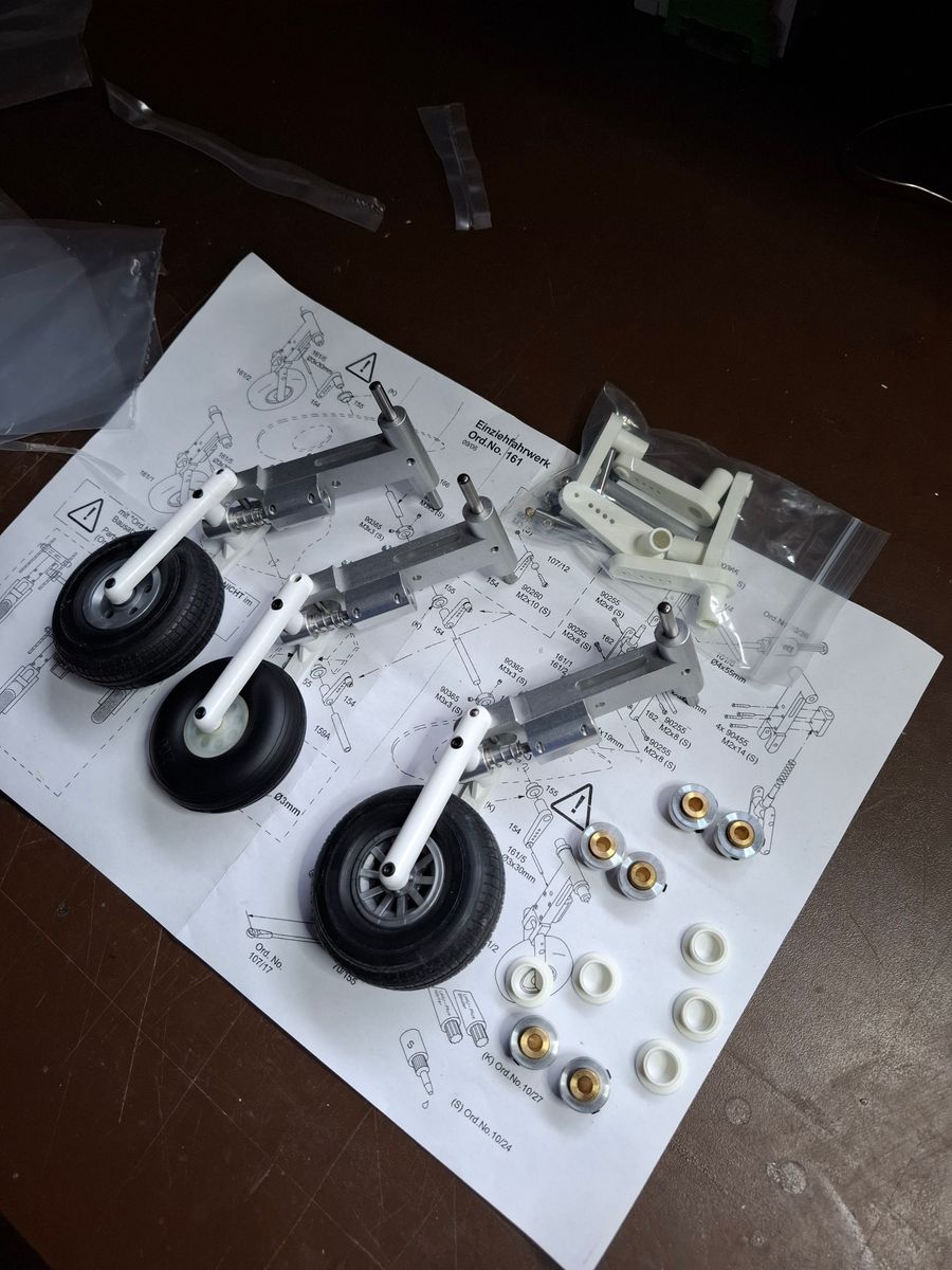
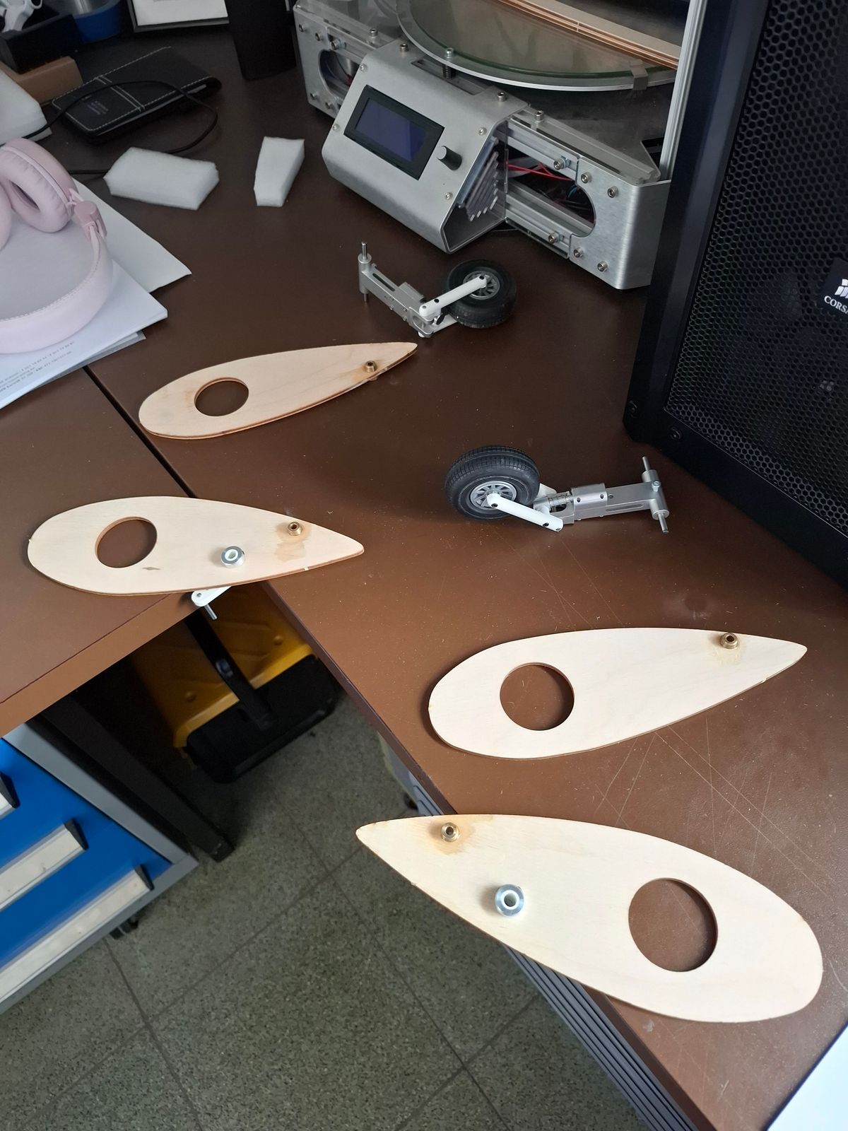
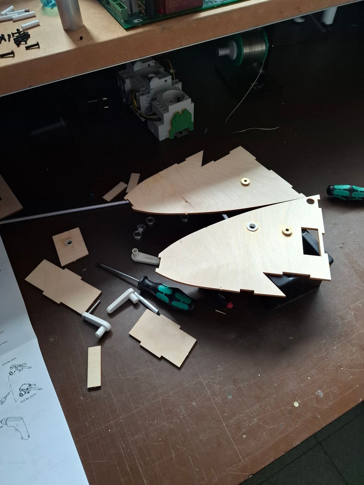
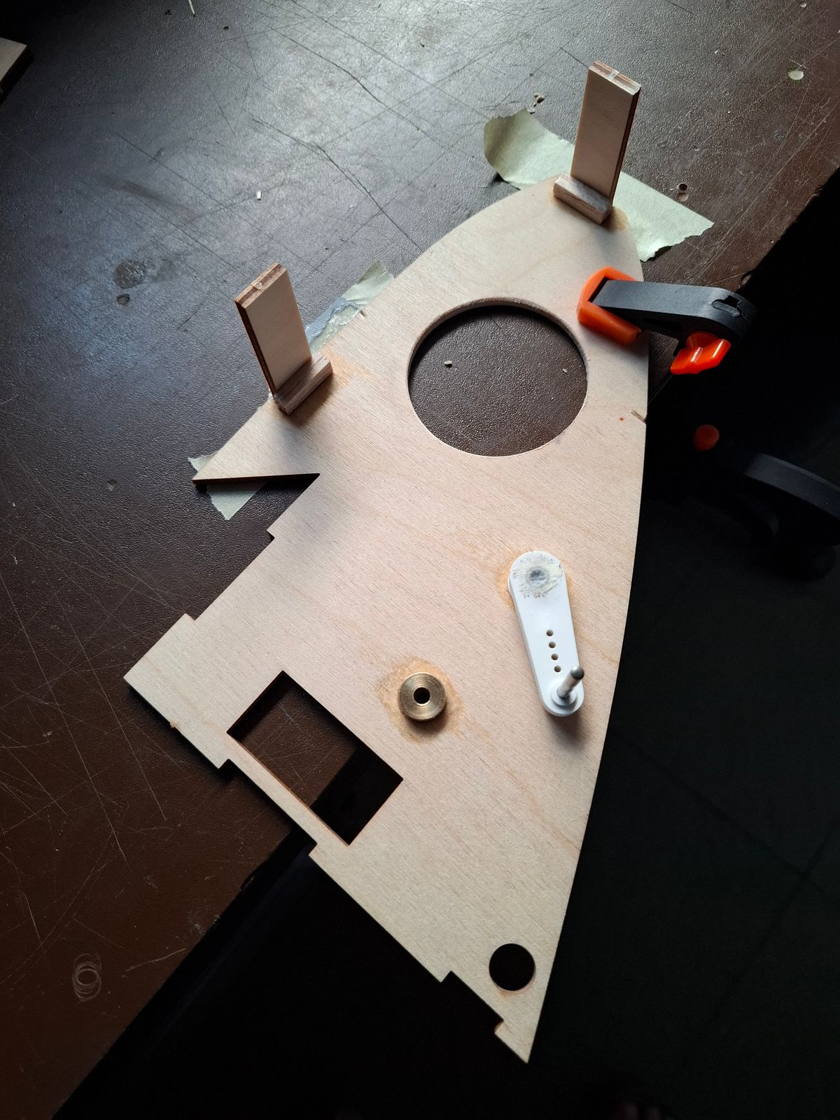
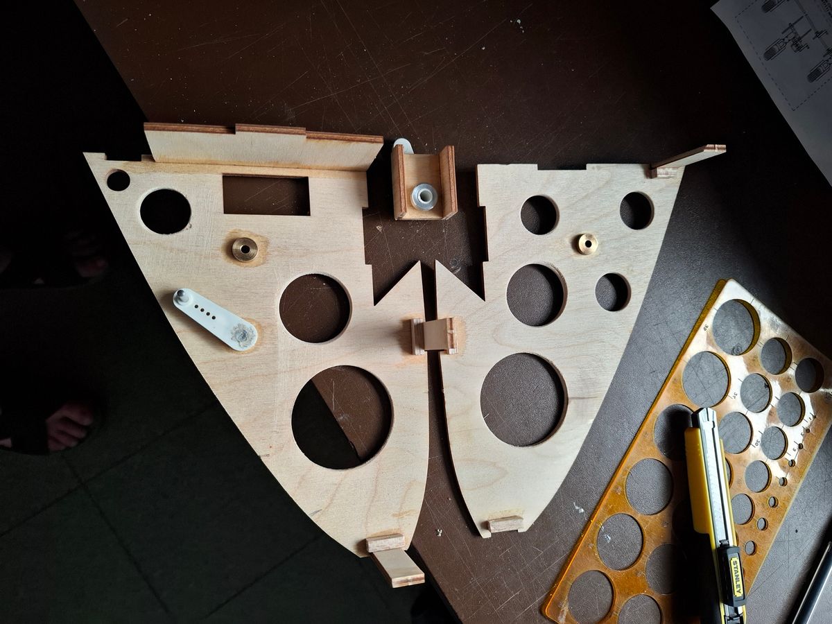
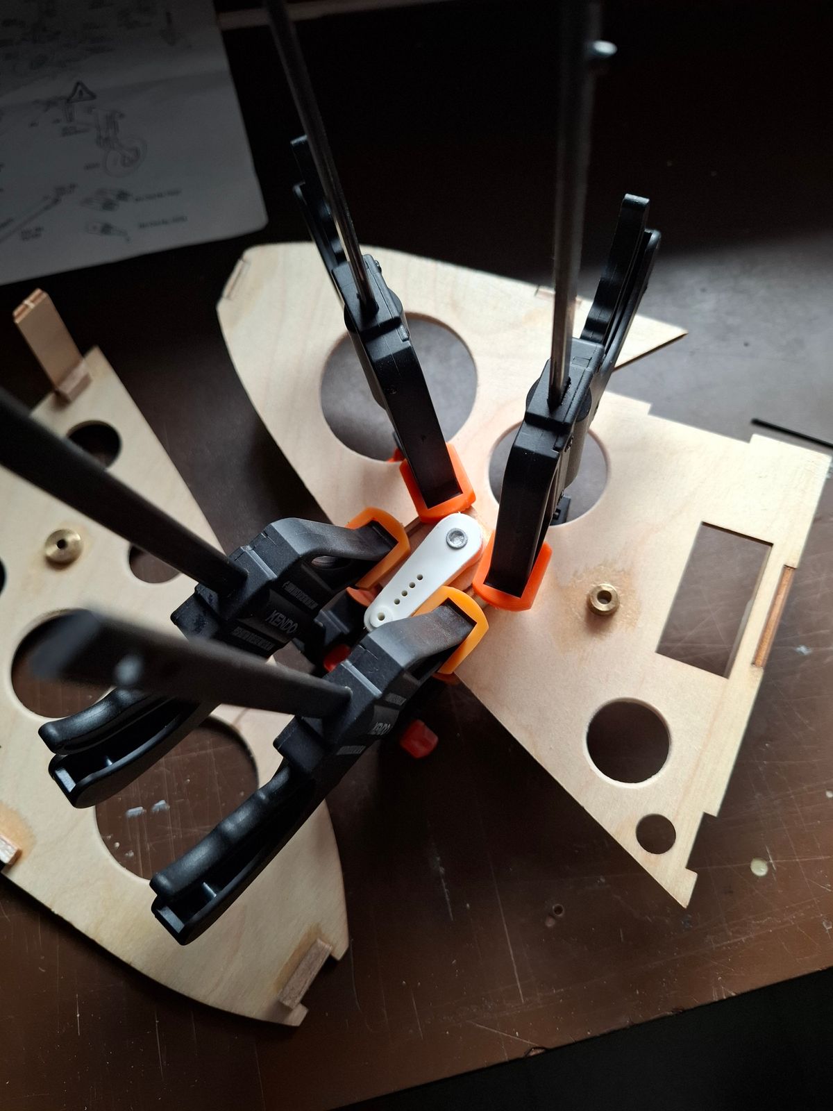
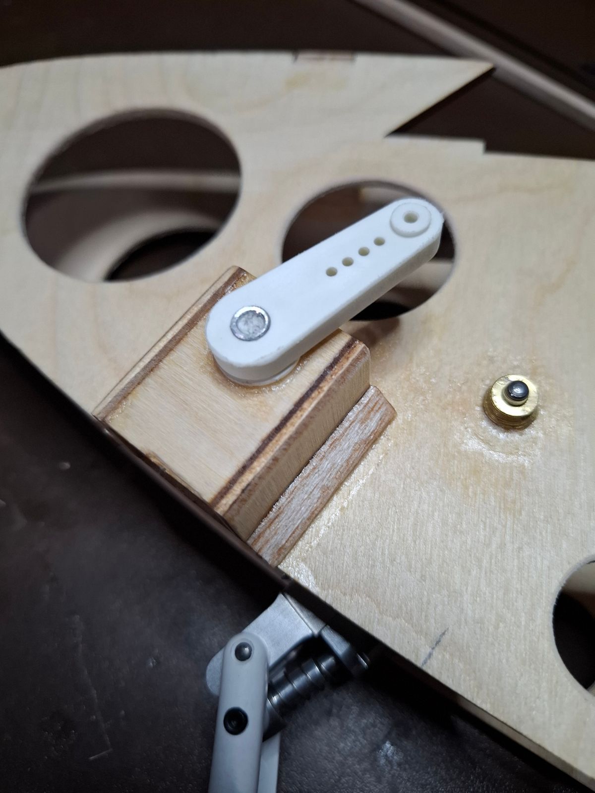
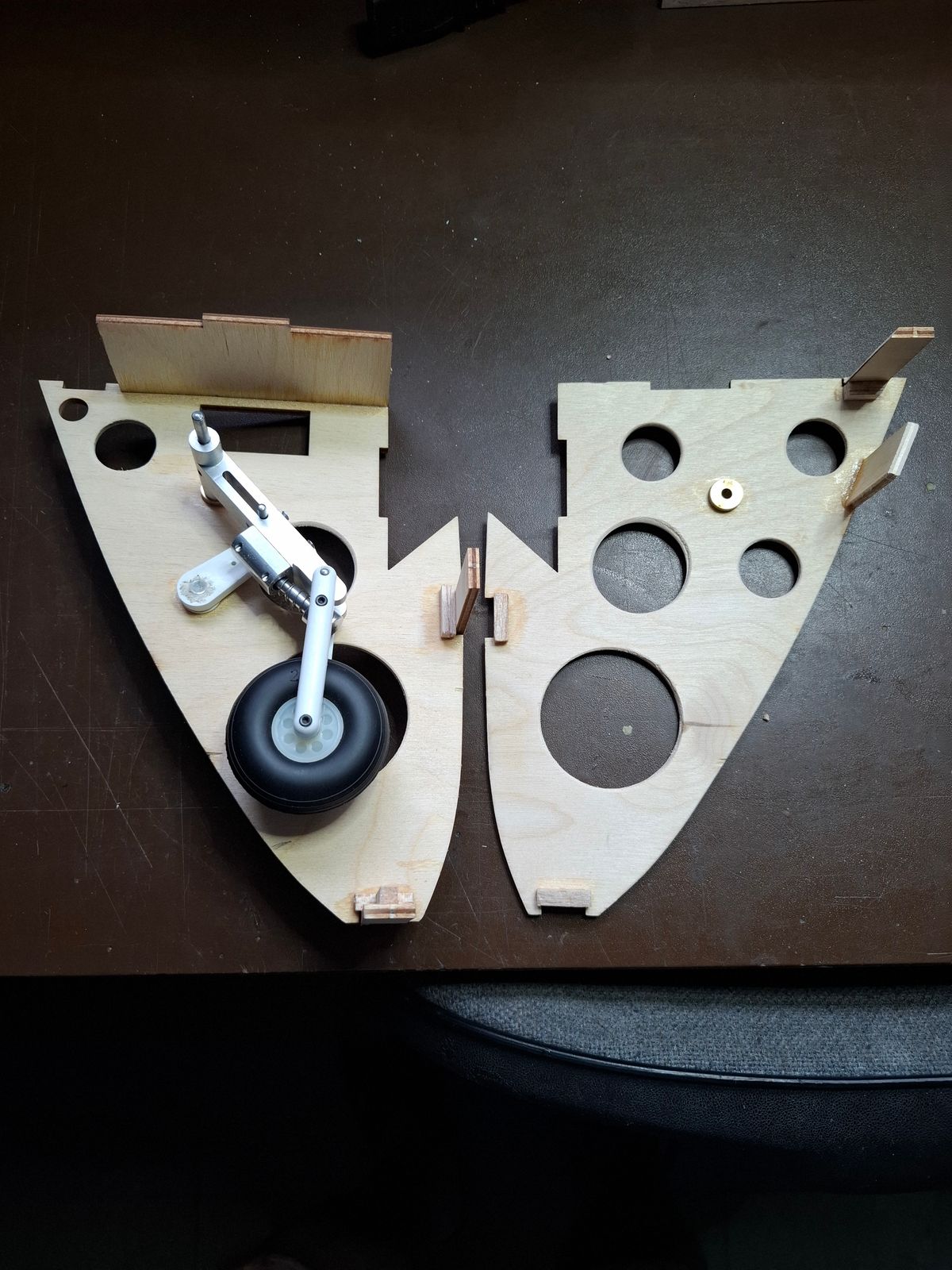
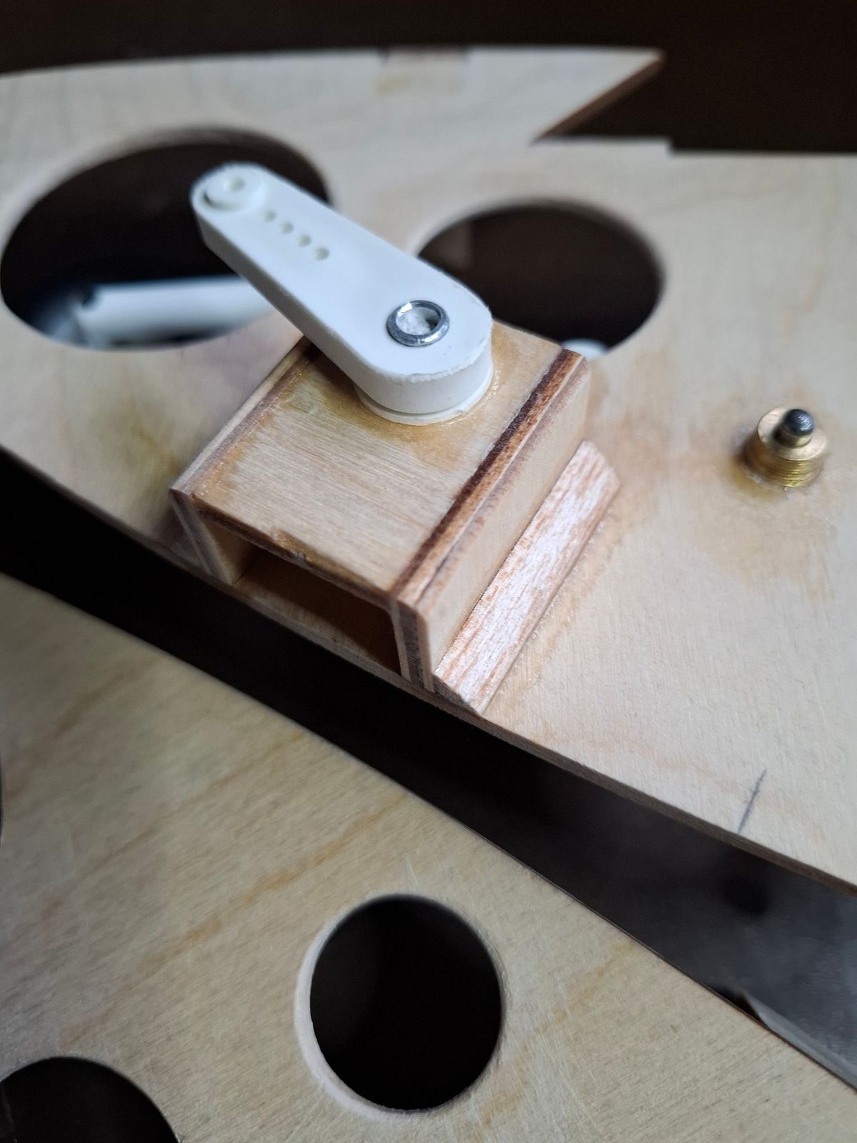
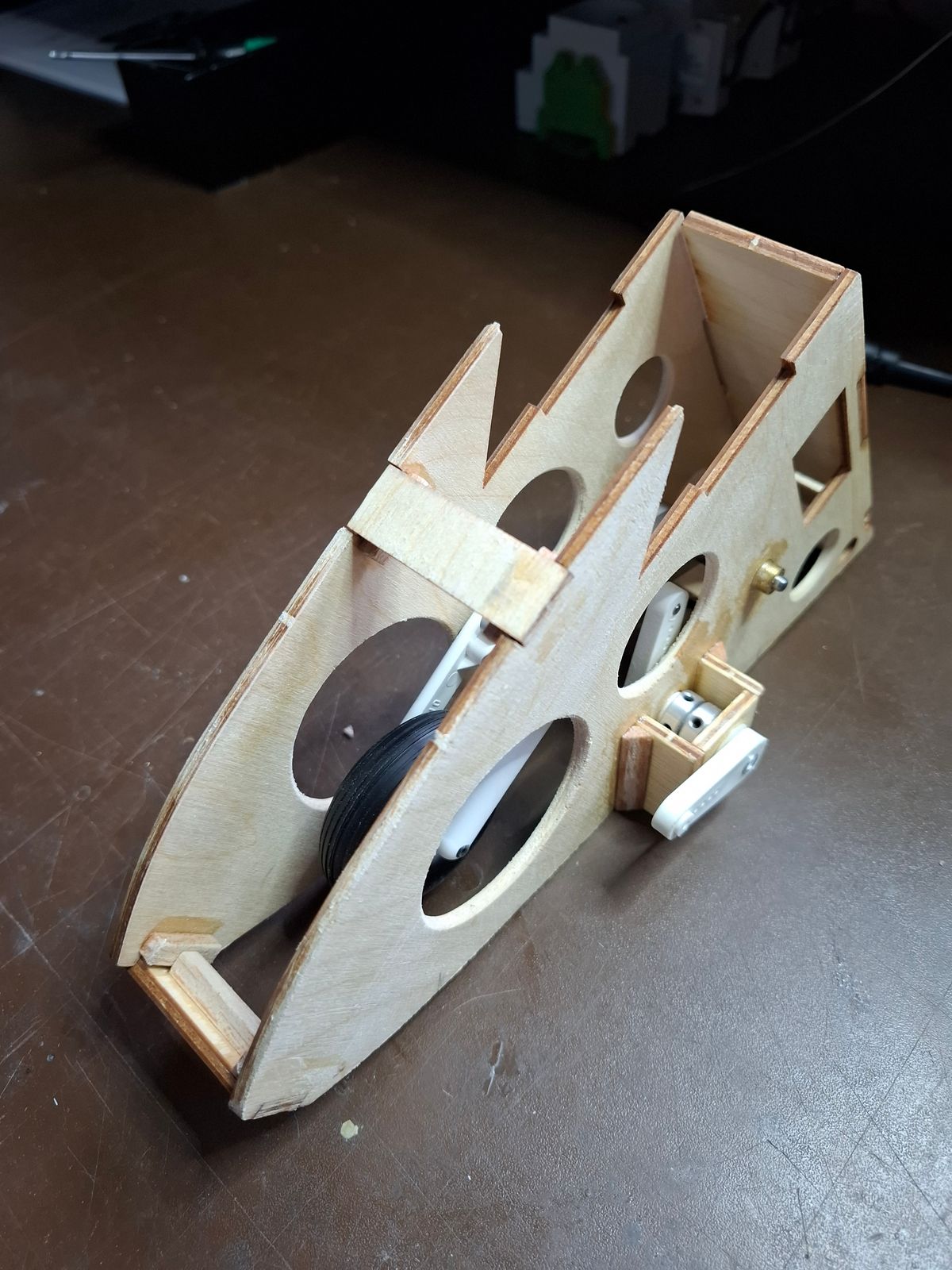
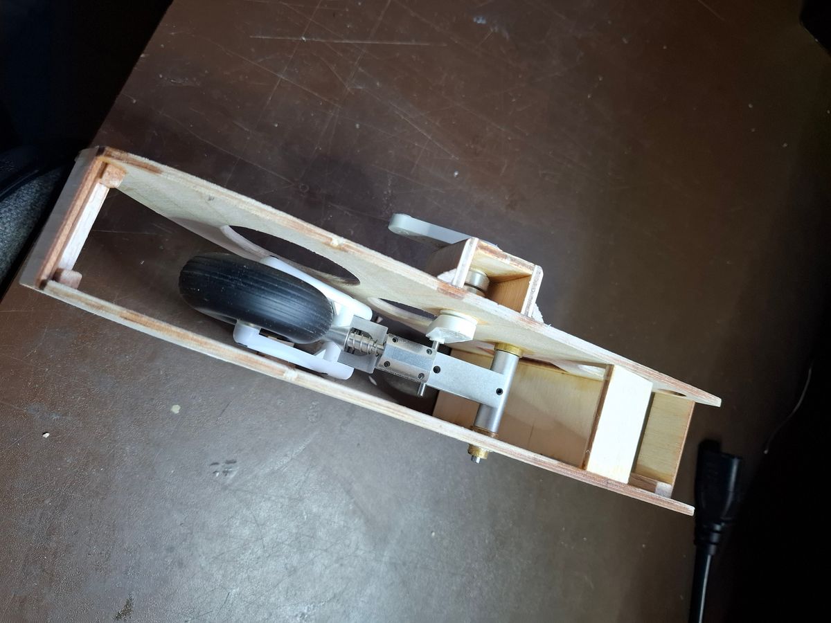
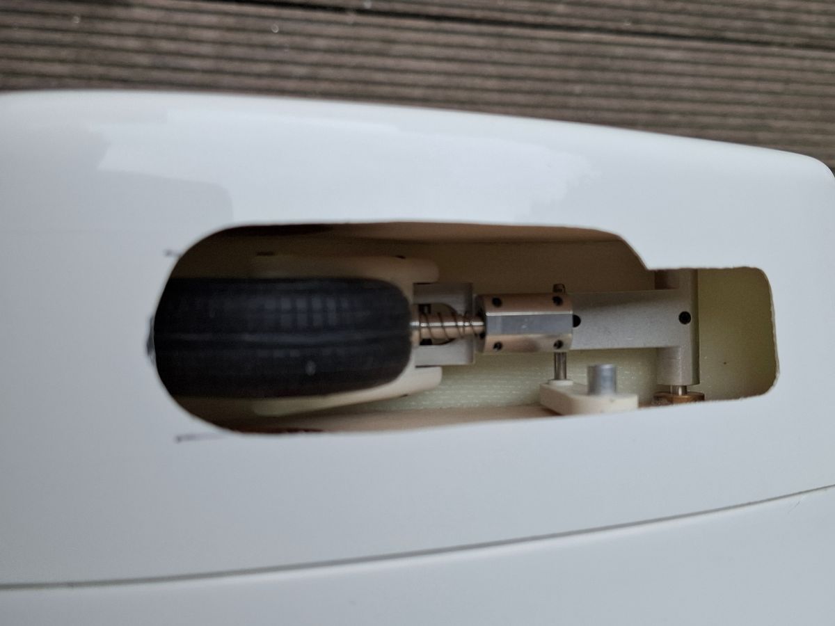
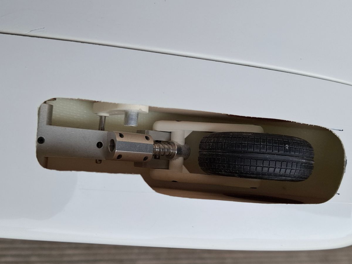
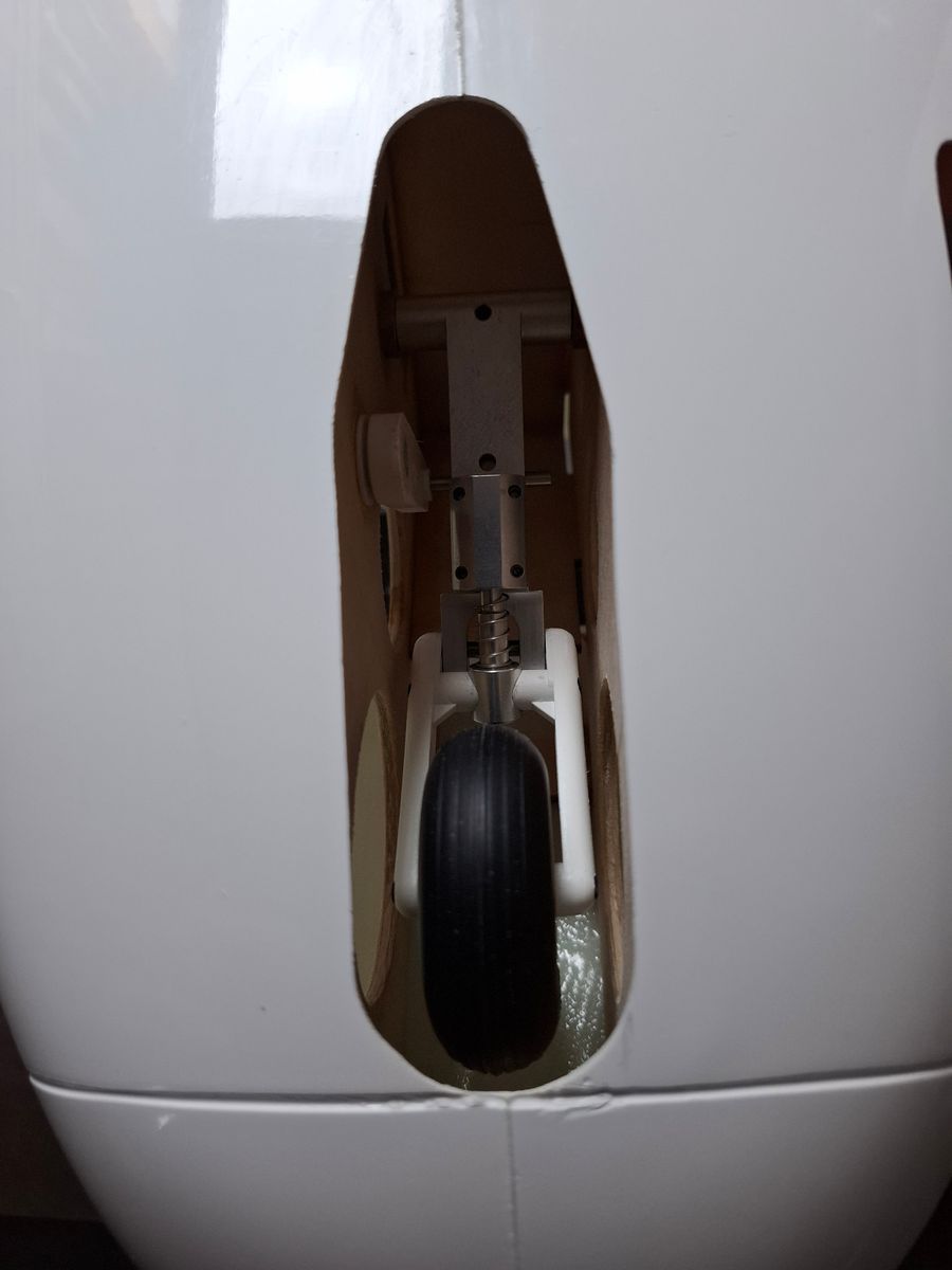
Started with the retract mechanics, lot's of puzzling and modifying the plywood to make it work smooth.
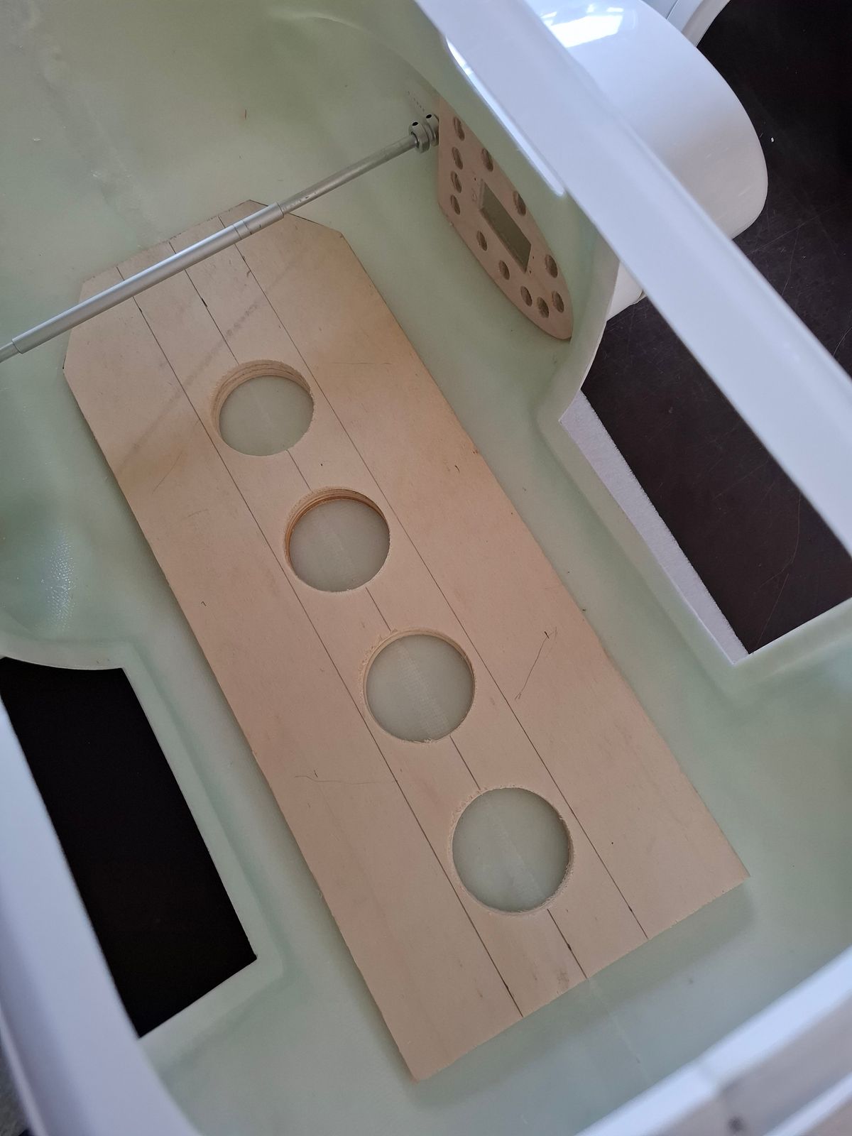
Saved some weight on the wood construction where possible, it all counts at the end.....
Some milling done....
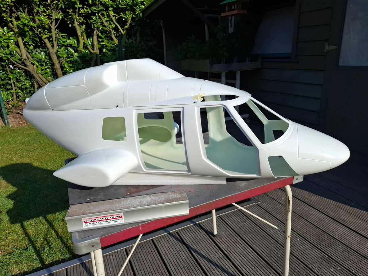
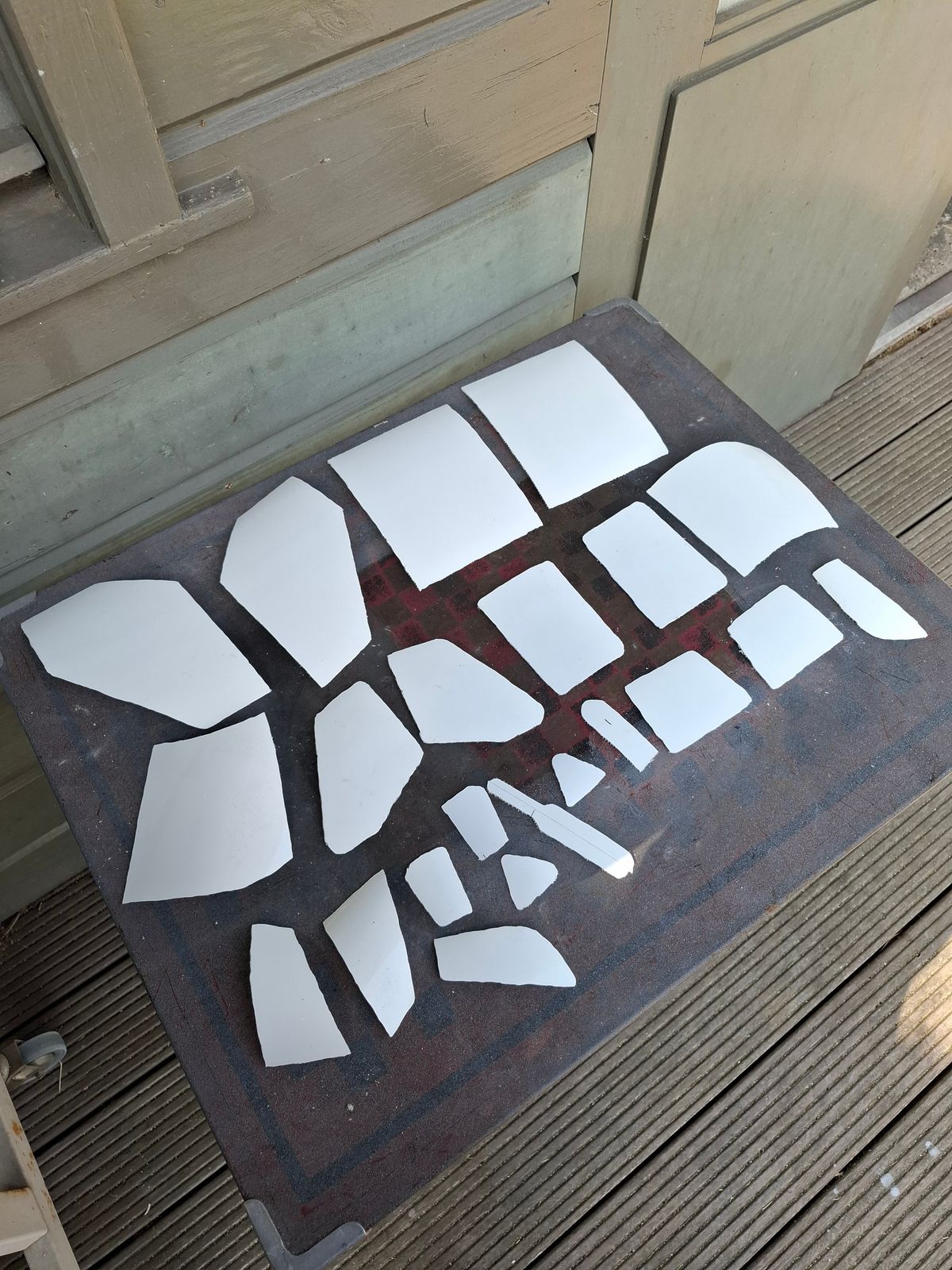
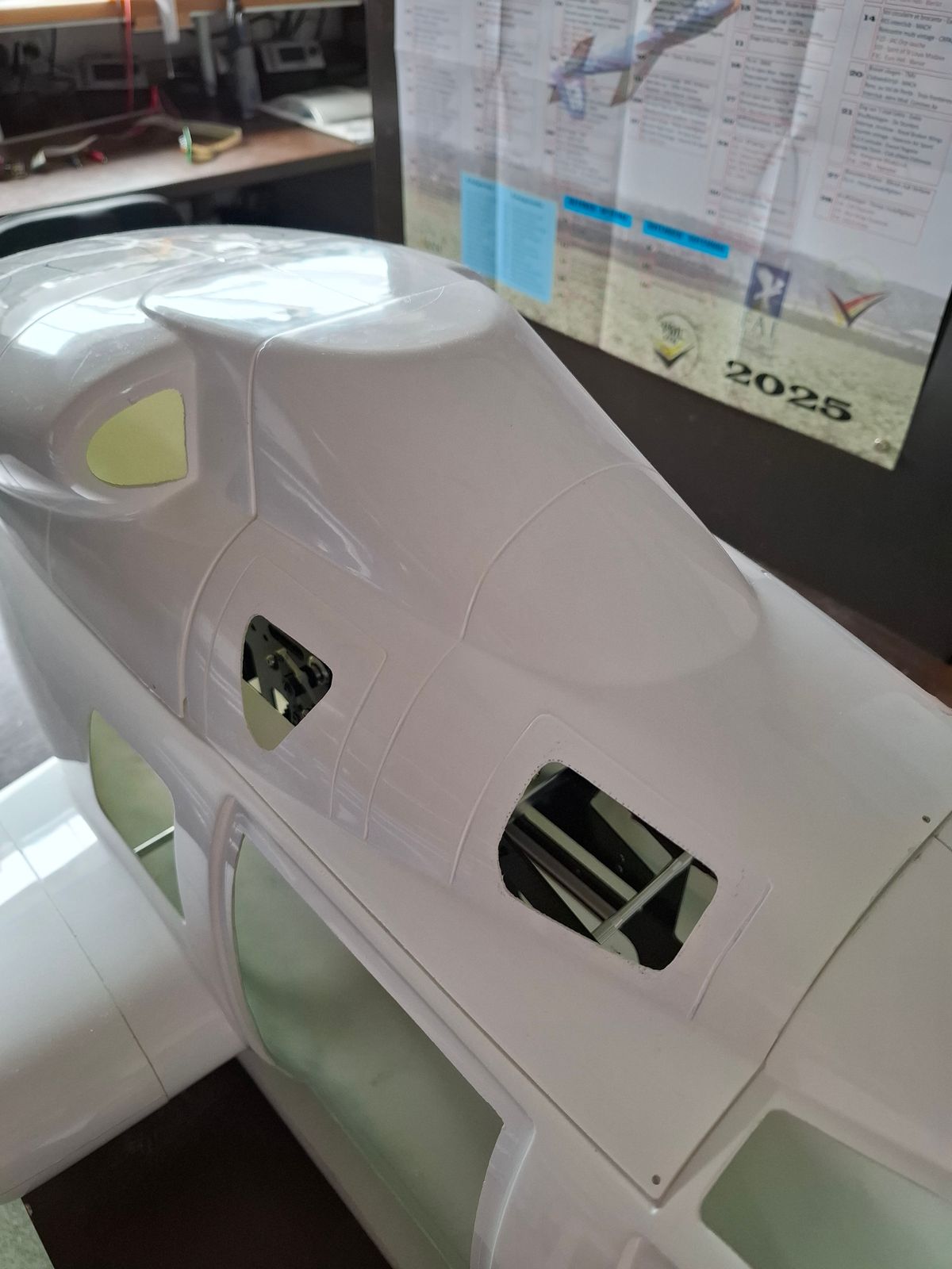
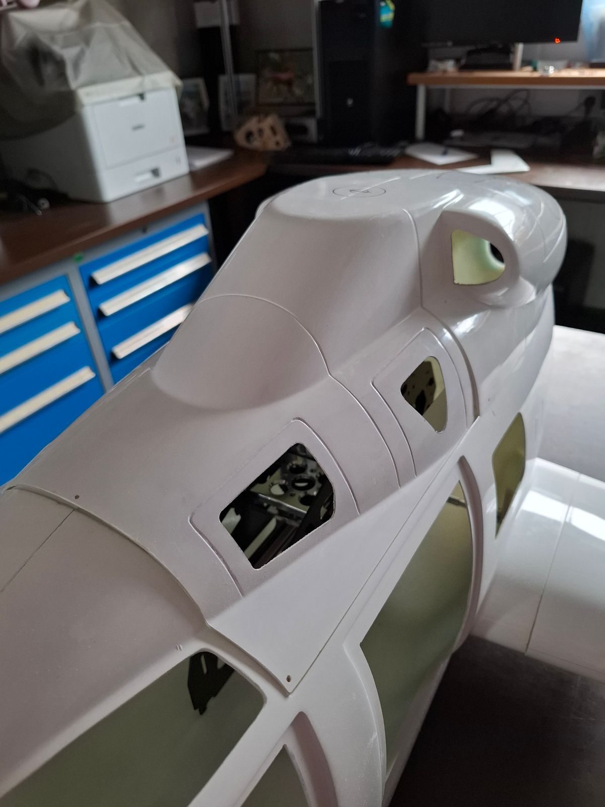
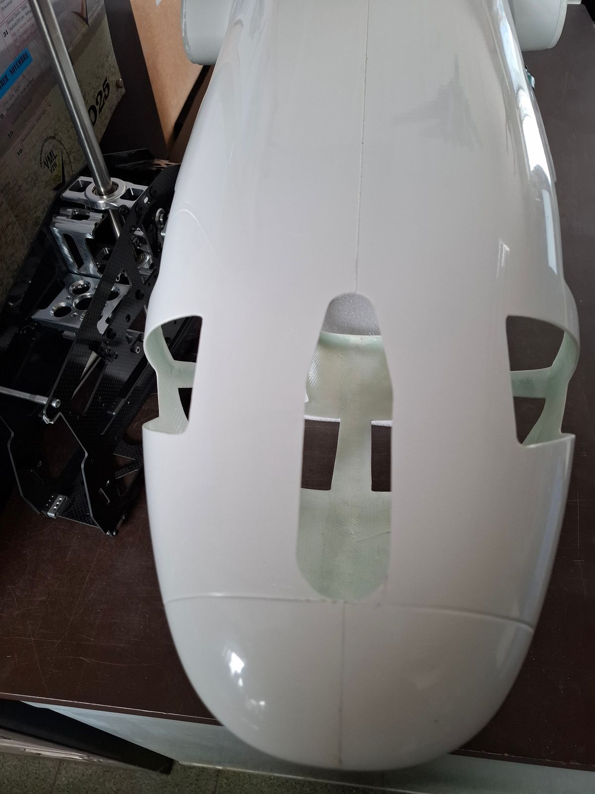
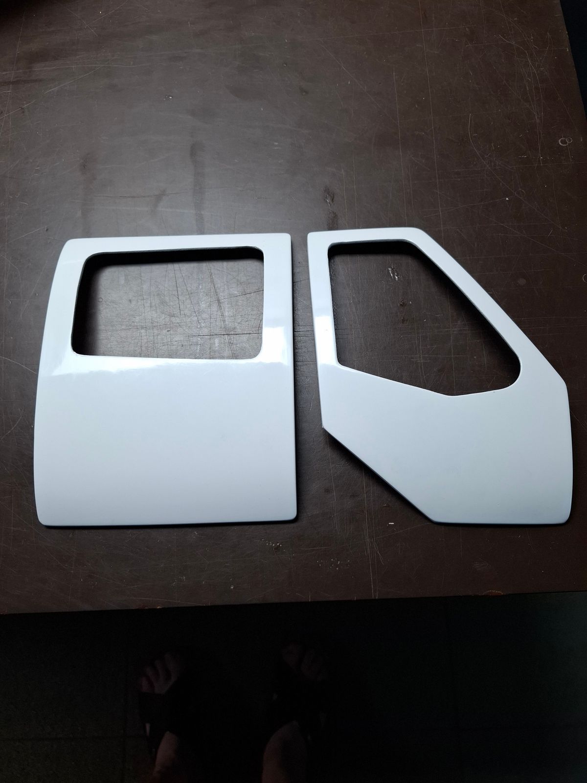
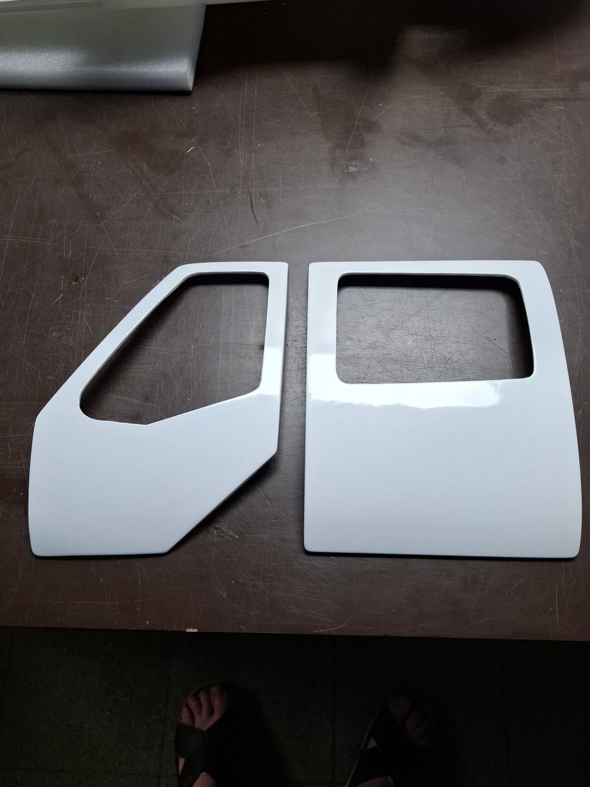
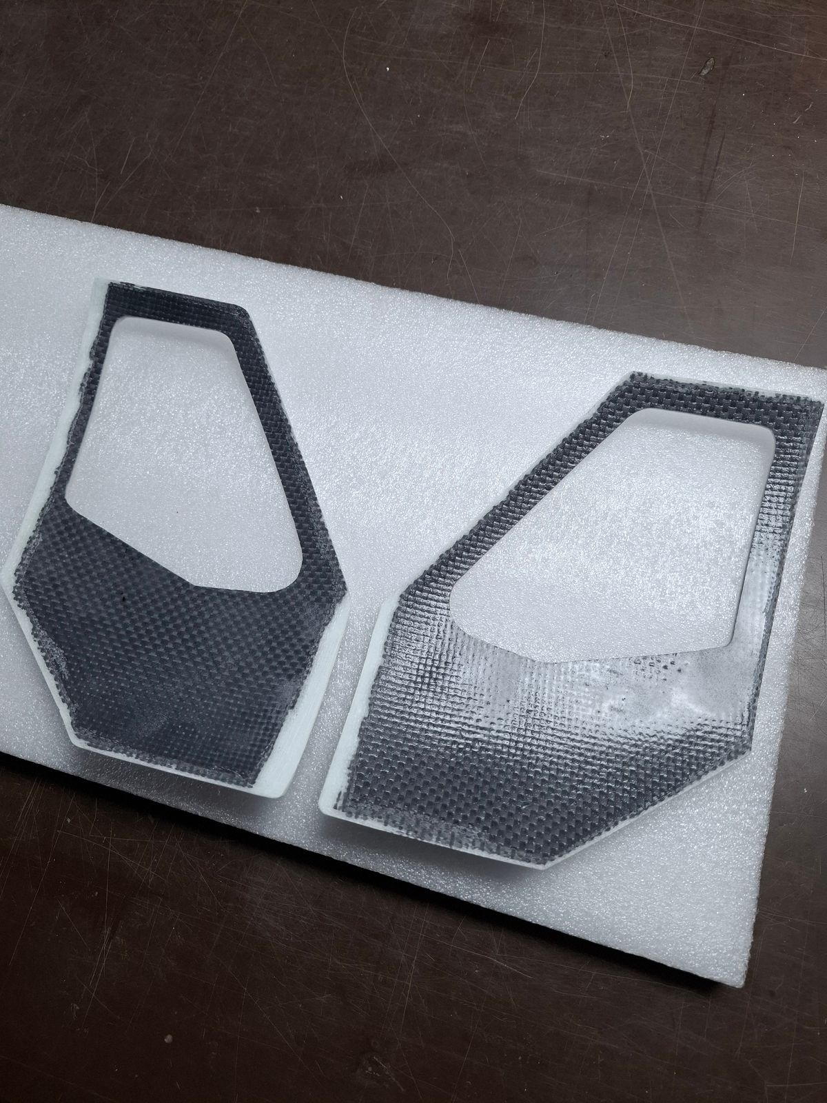
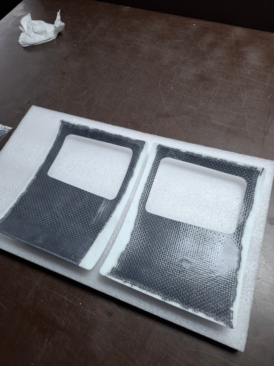
Milling doors, windows, vents and retract openings.
Hell of a job.
Adapting the doors so that they nicely fit the fuselage opening contours.
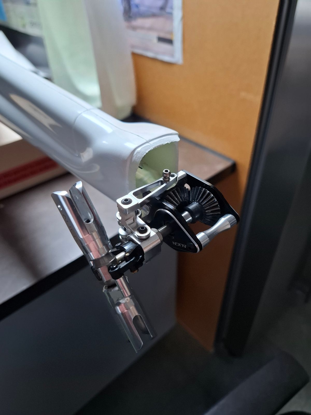
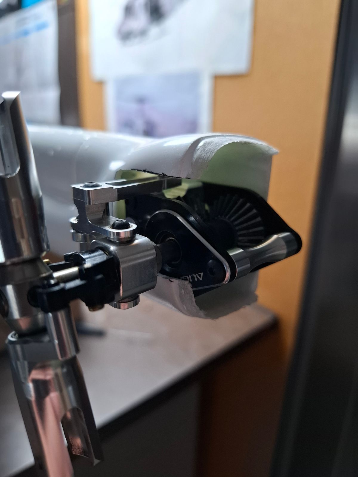
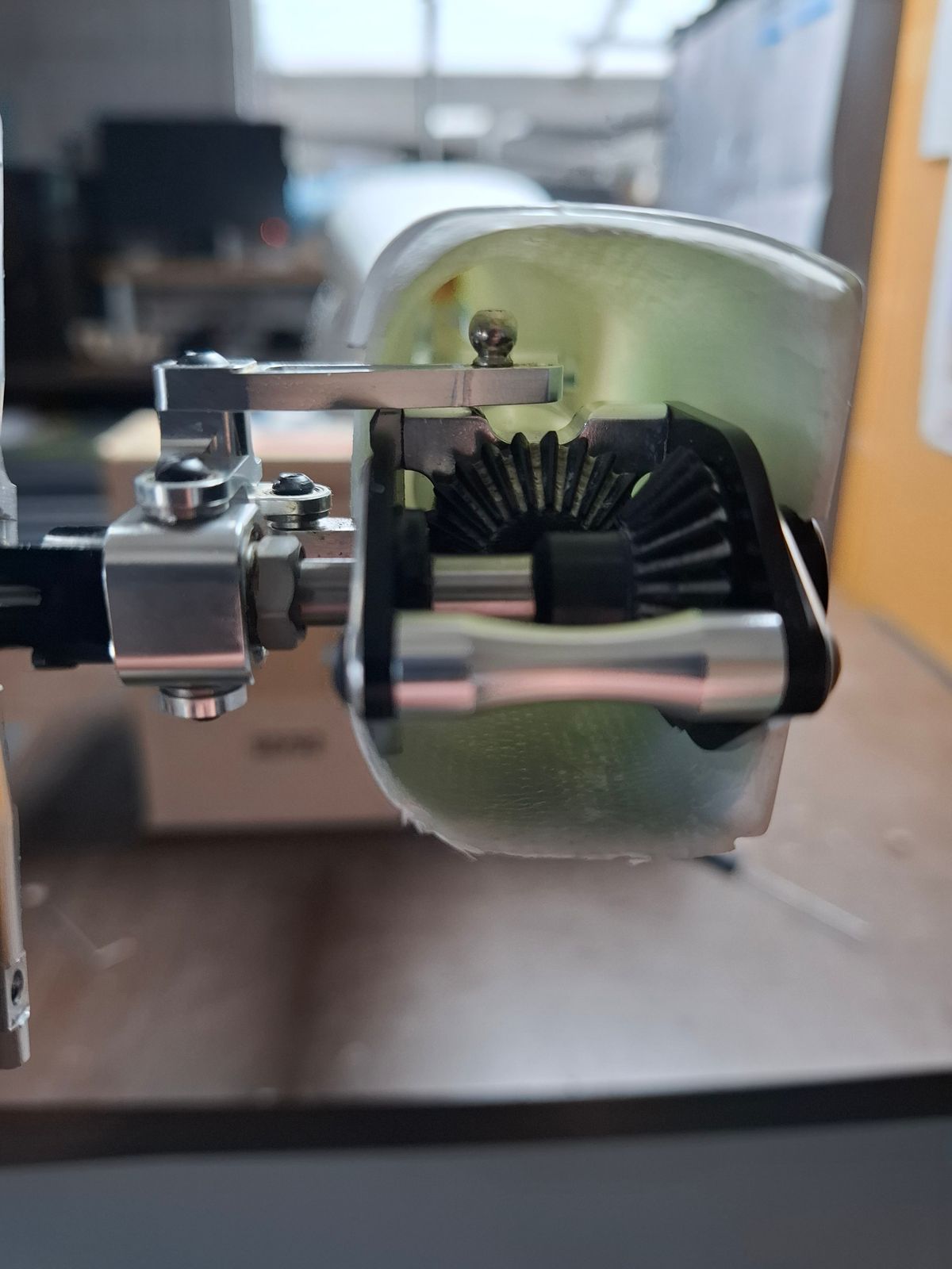
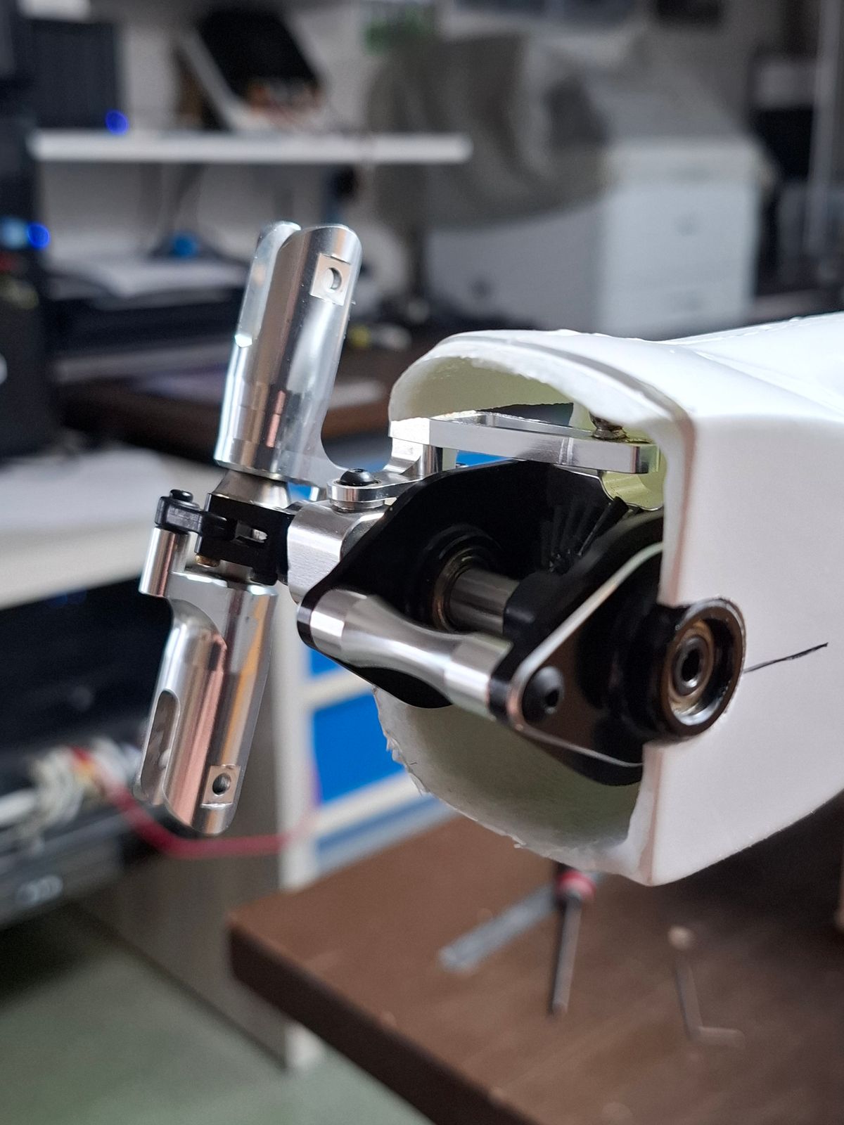
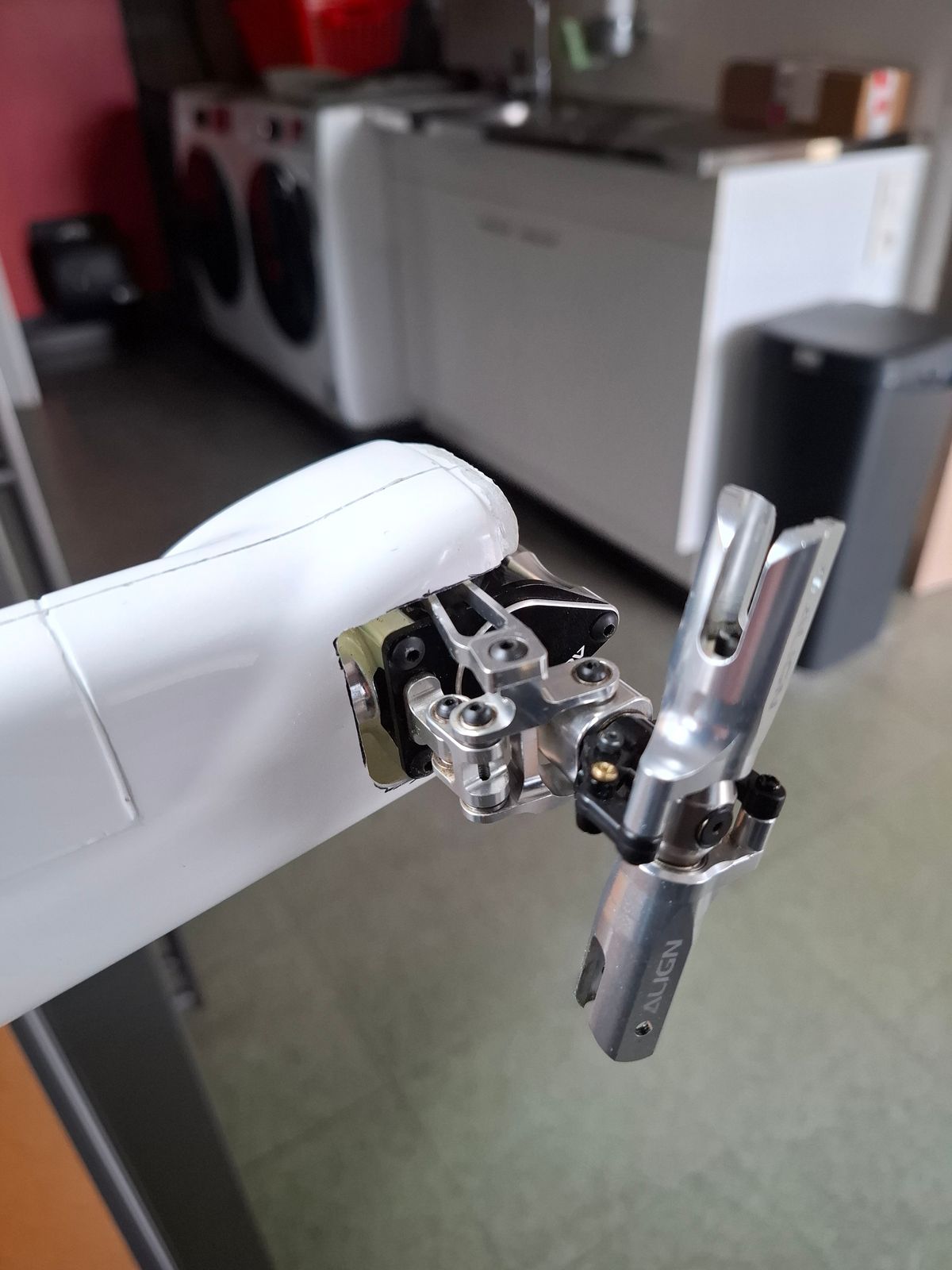
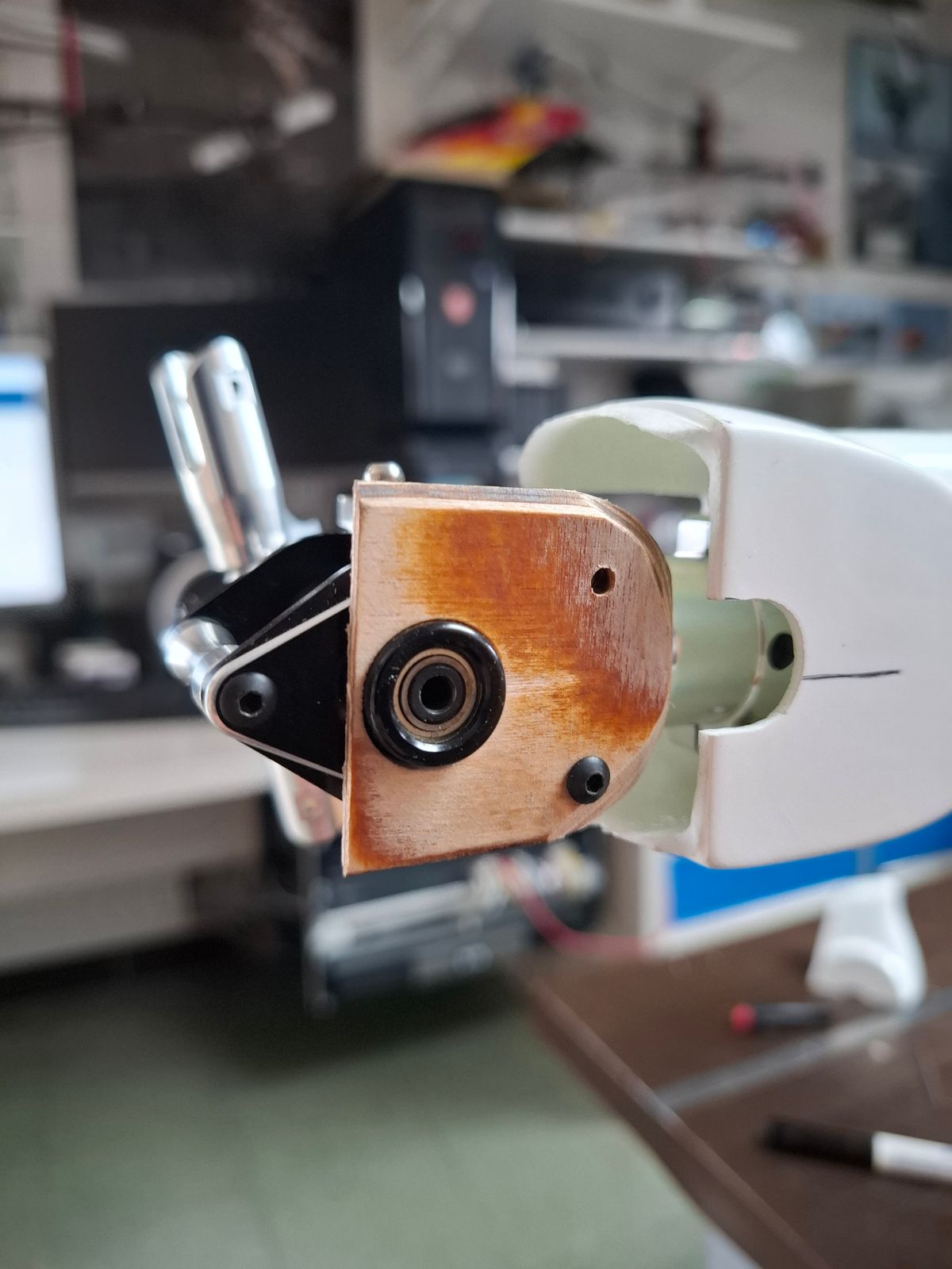
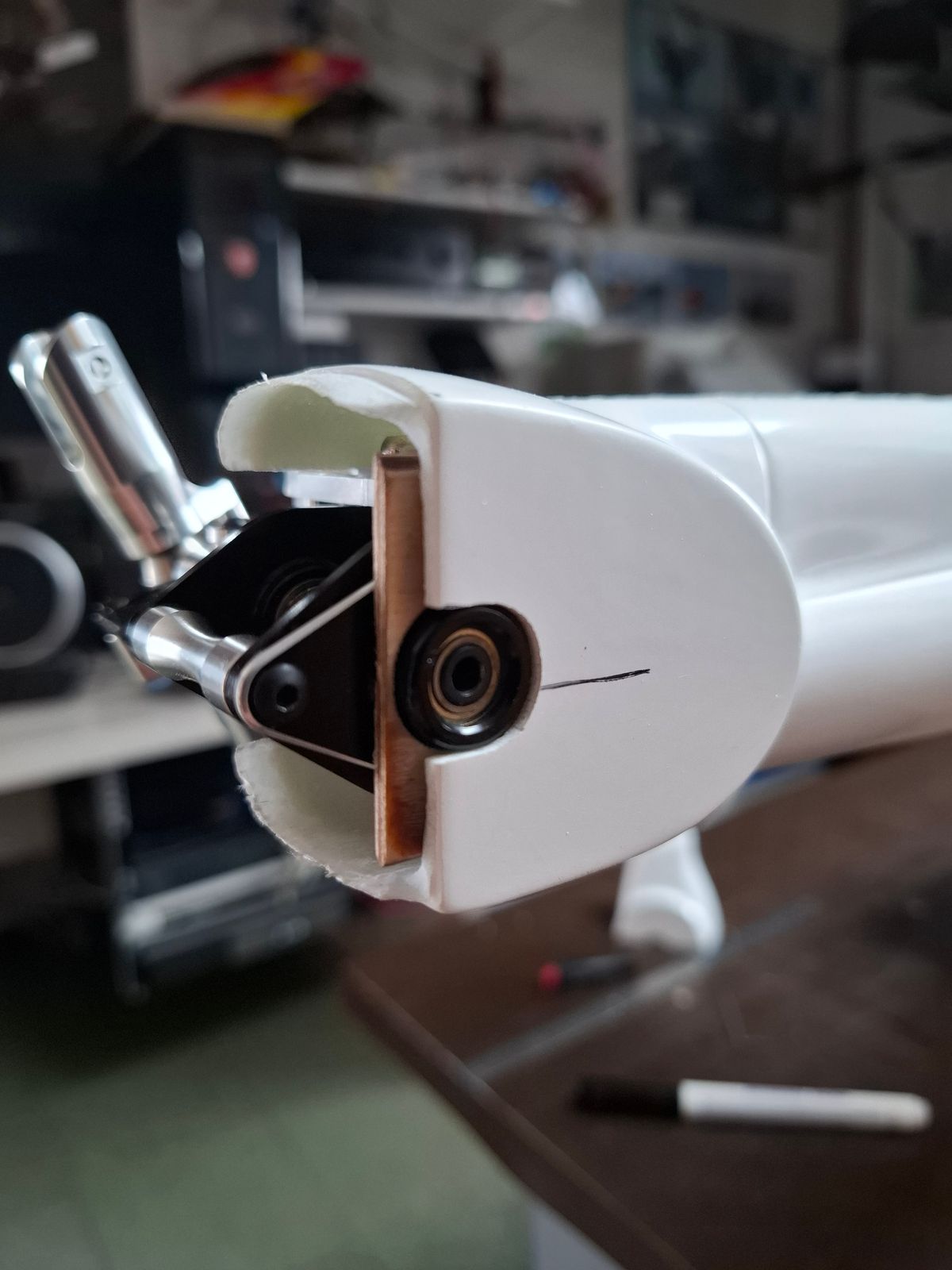
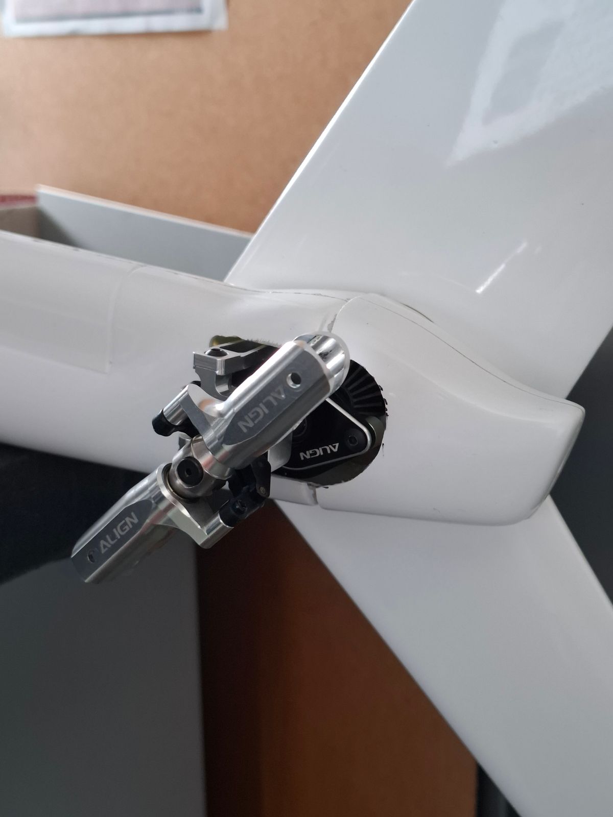
Tail rotor installation and modification.
Adapting and installation of the tail rotor housing.
The tail rotor has to be installed inverted to be scale true, so pitch control on the upper side.
Modification of the rudder control arm bridge, lower the control arm due to the narrow tail boom end.
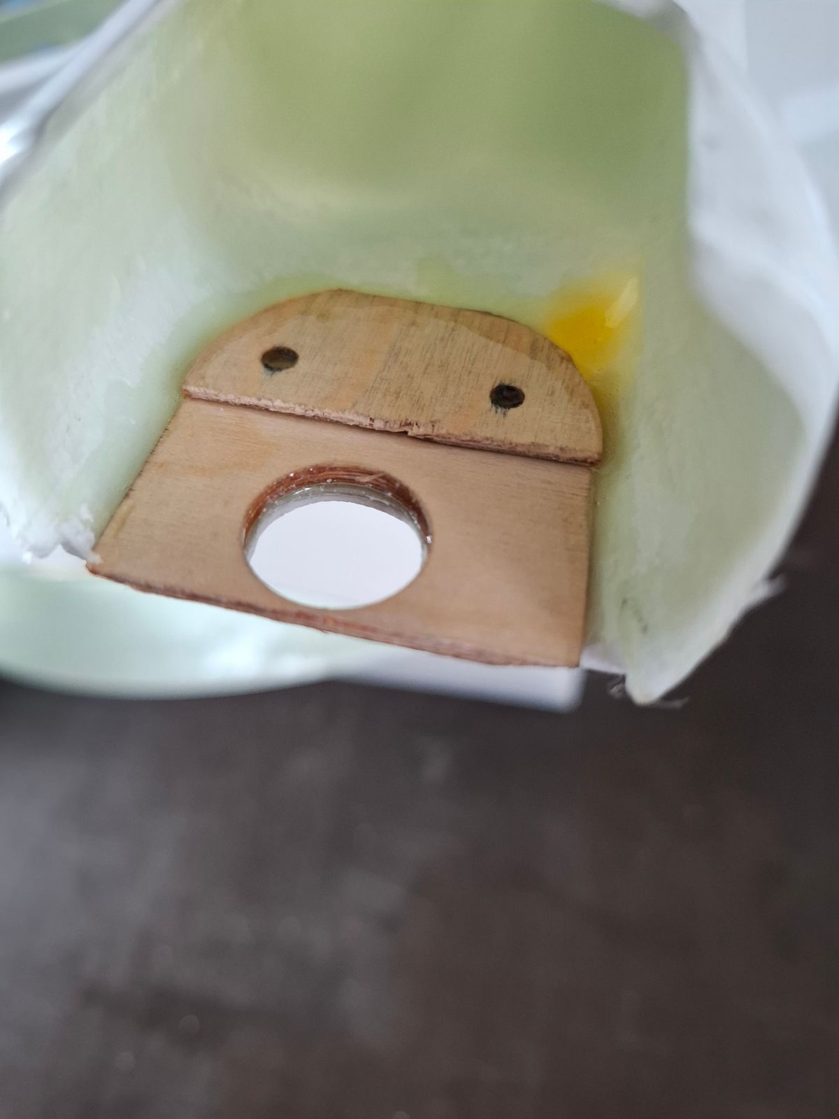
Solid rock fixture of the gearbox in the tail boom fuselage.
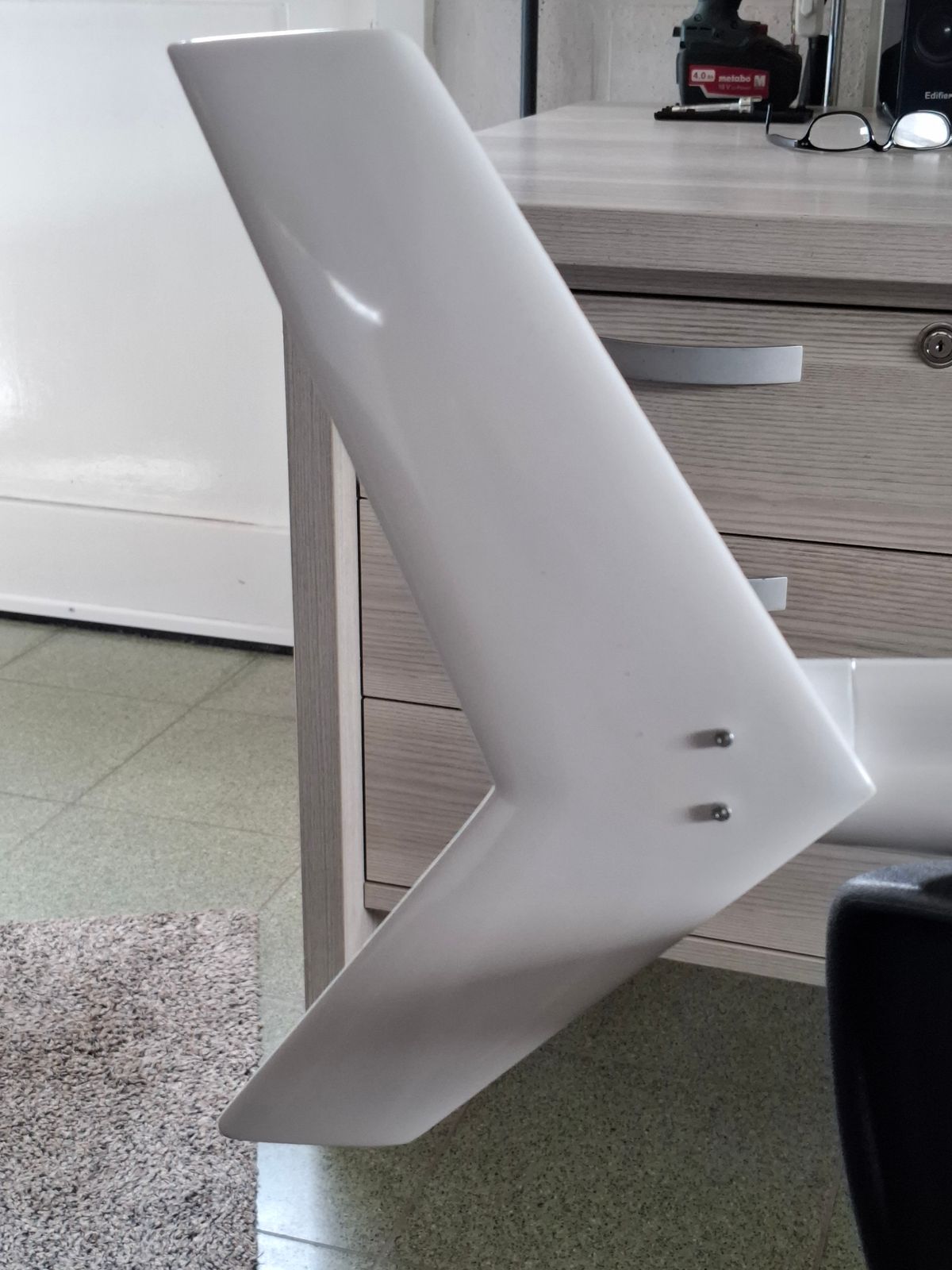
Tail fin fixed straight on the gearbox with the tail boom fuselage in between.
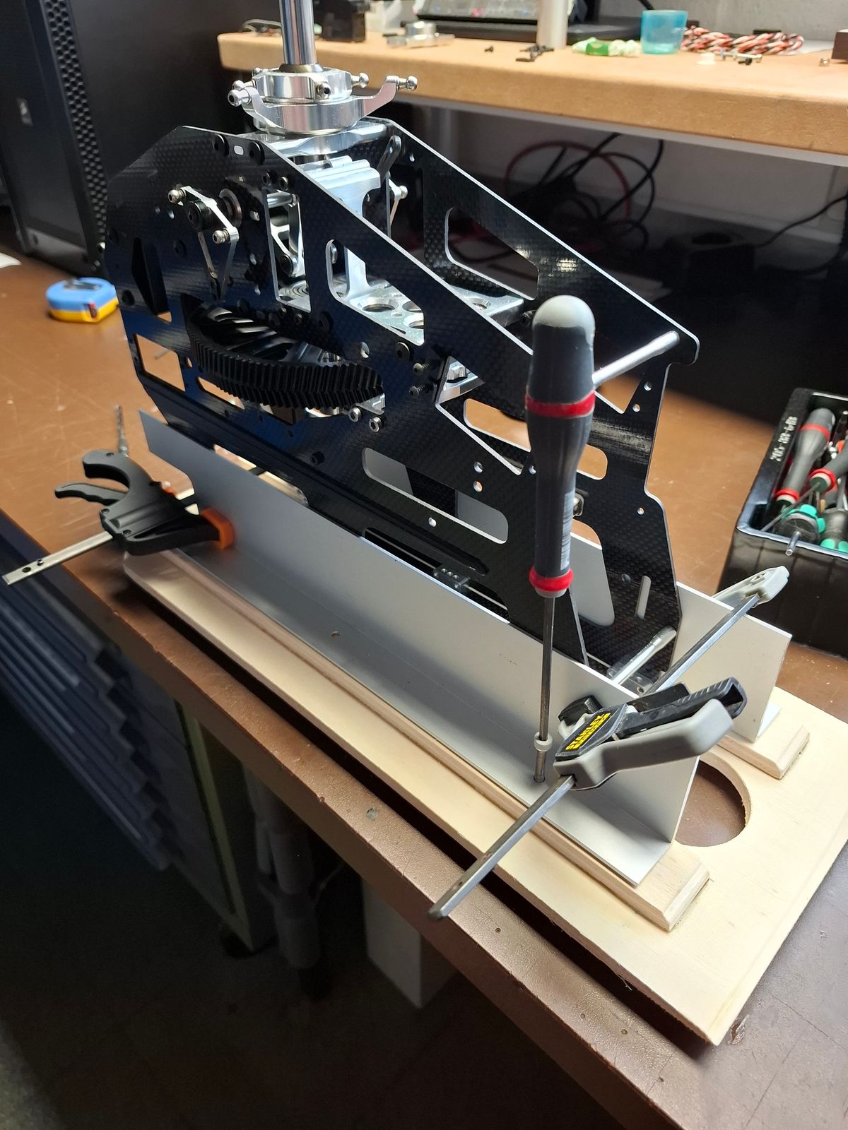
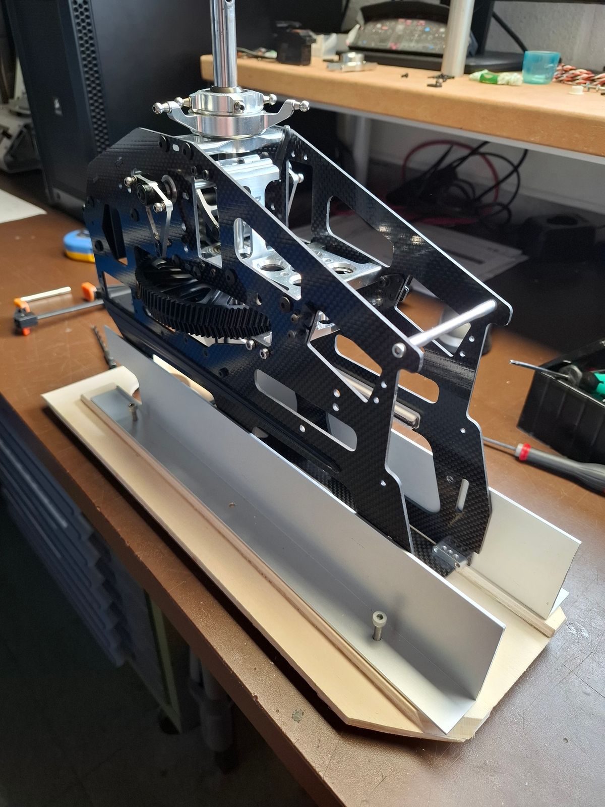
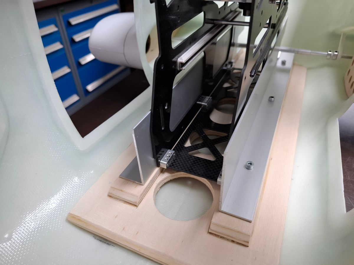
Baseframe construction
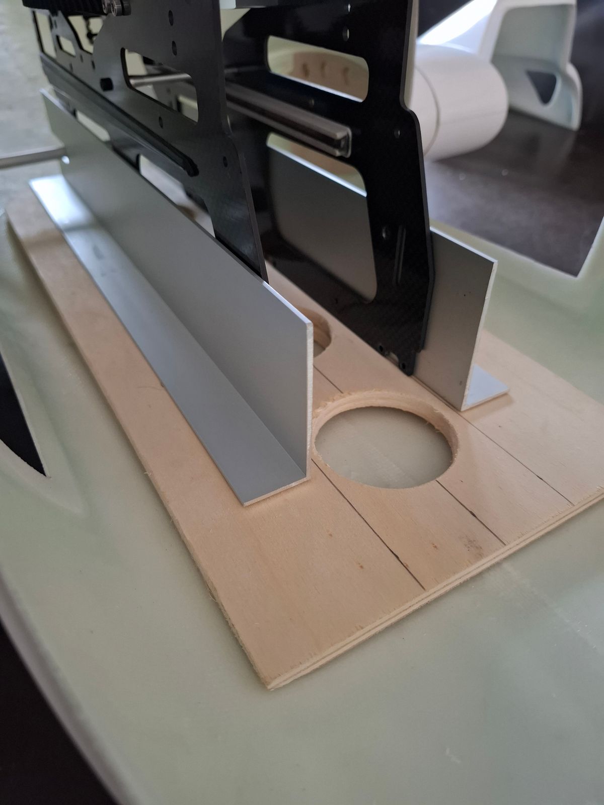
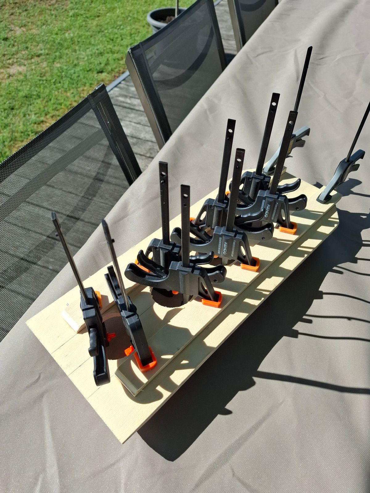
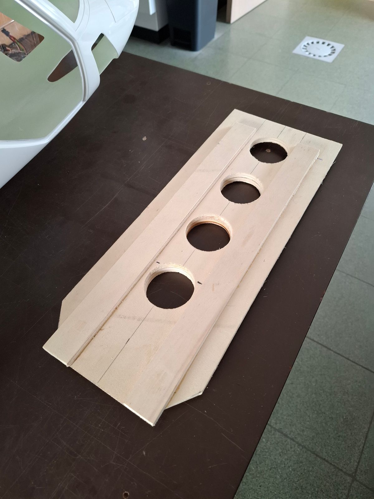
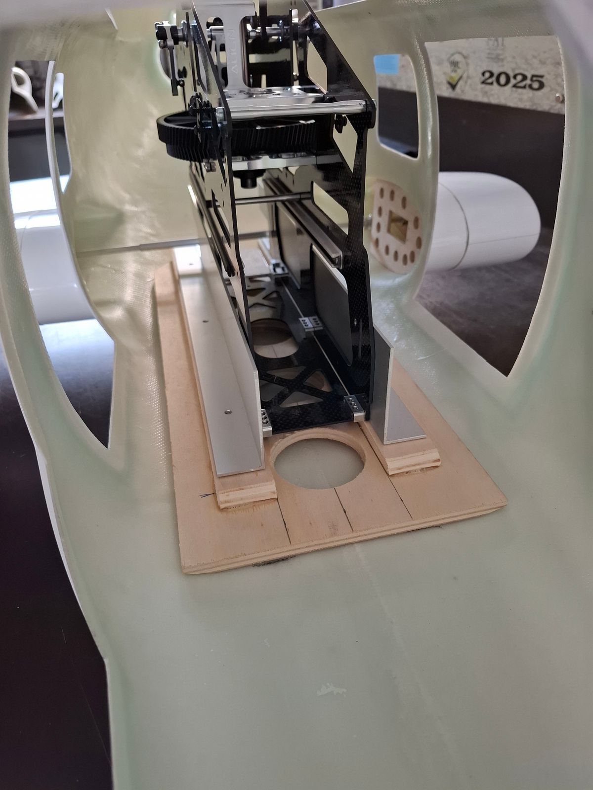
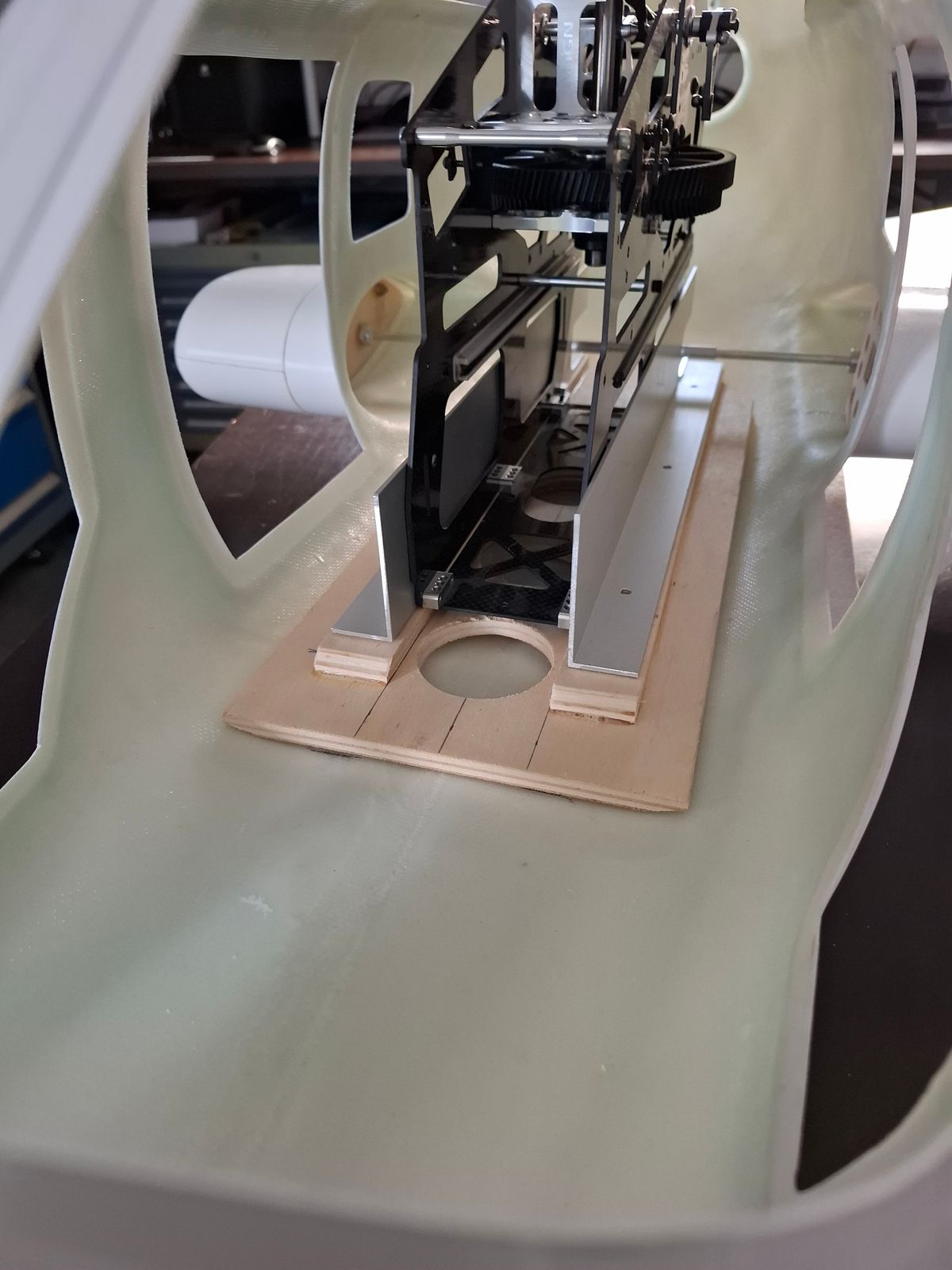
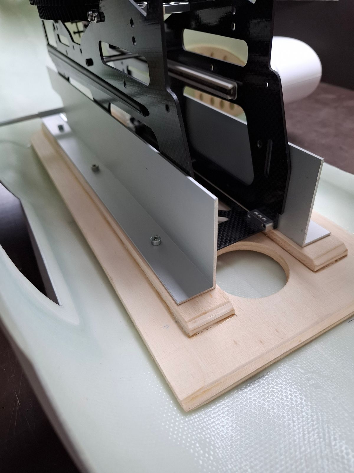
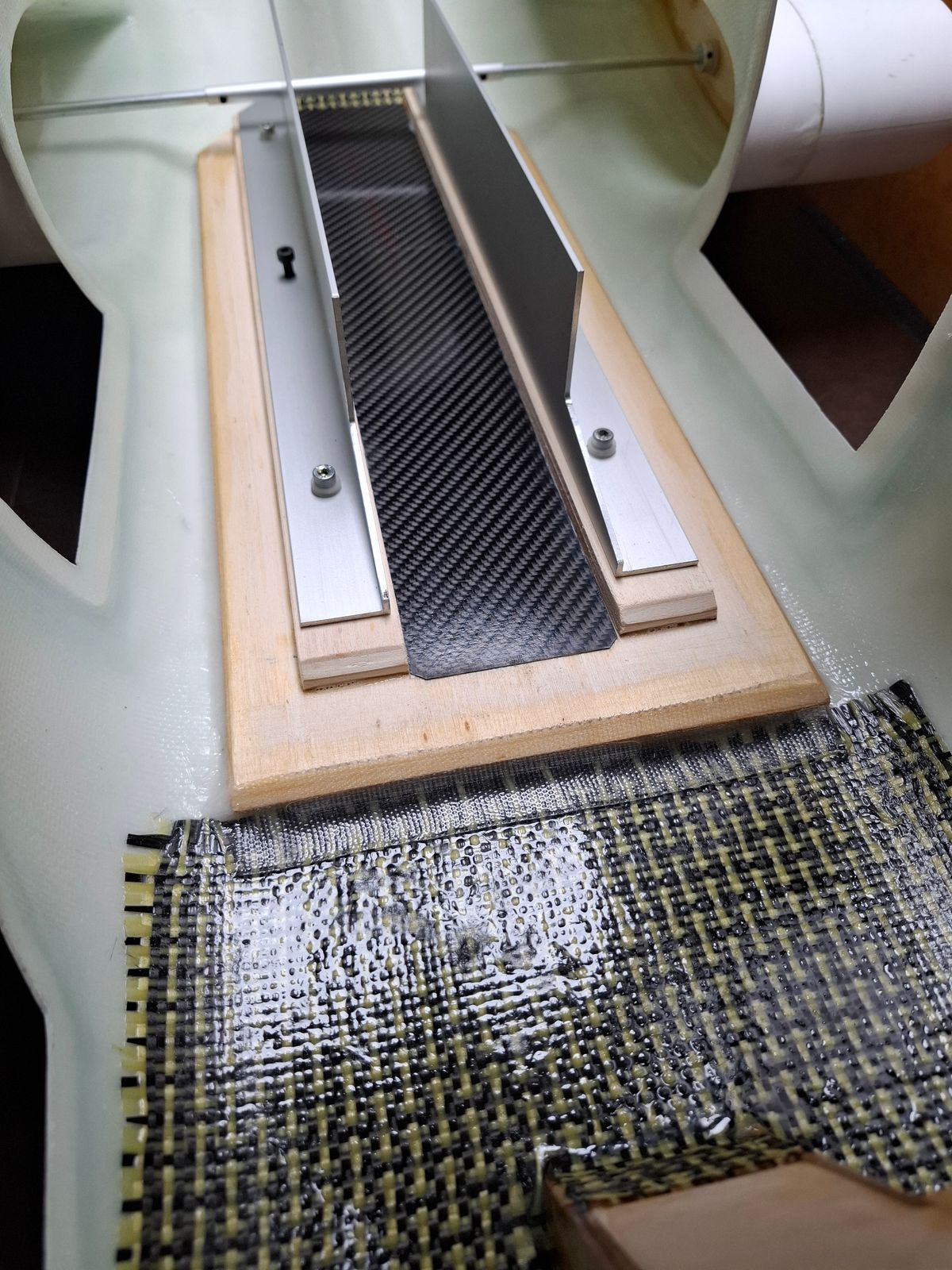
Construction of the wooden baseframe for support of the mechanics.
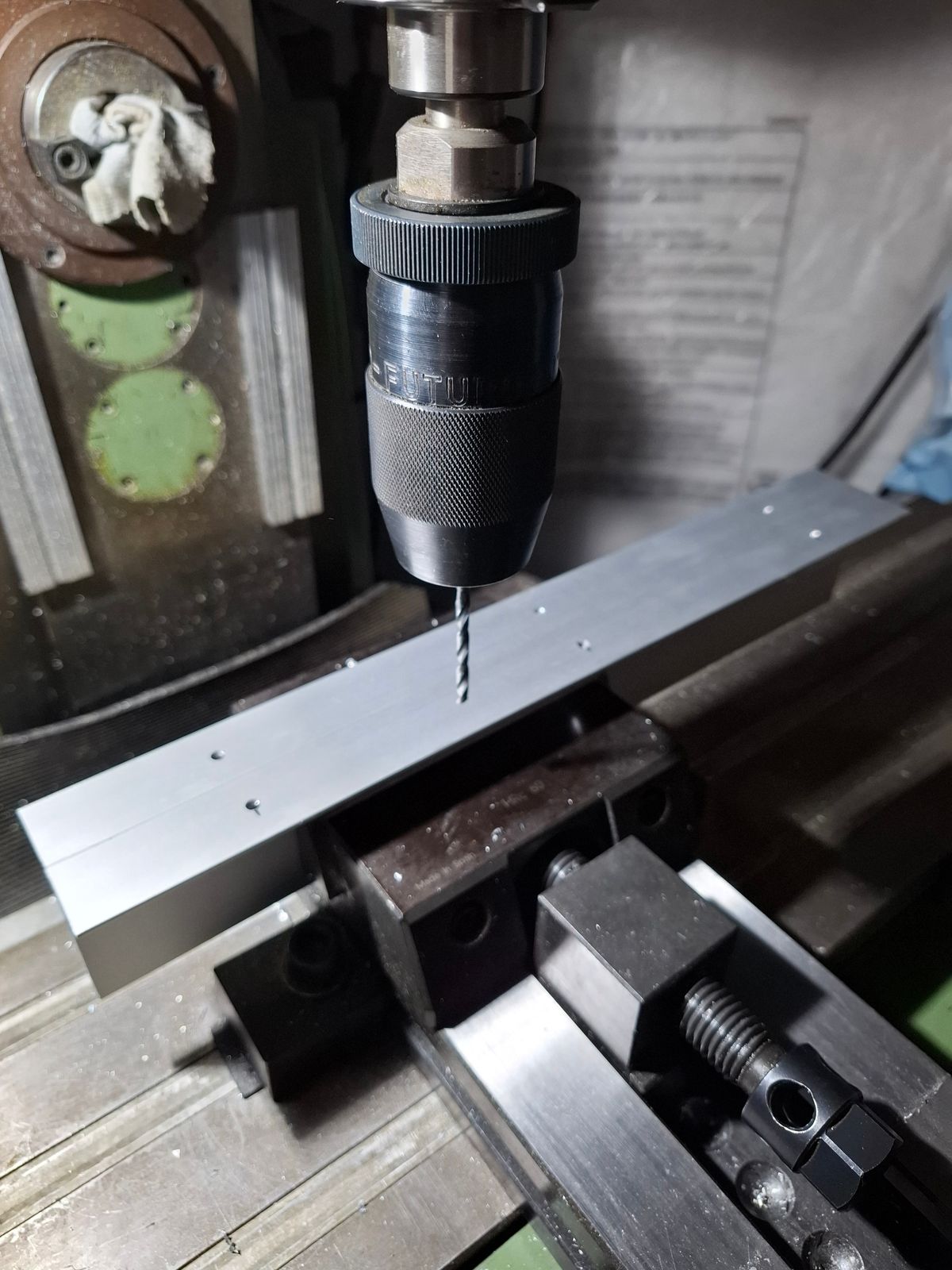
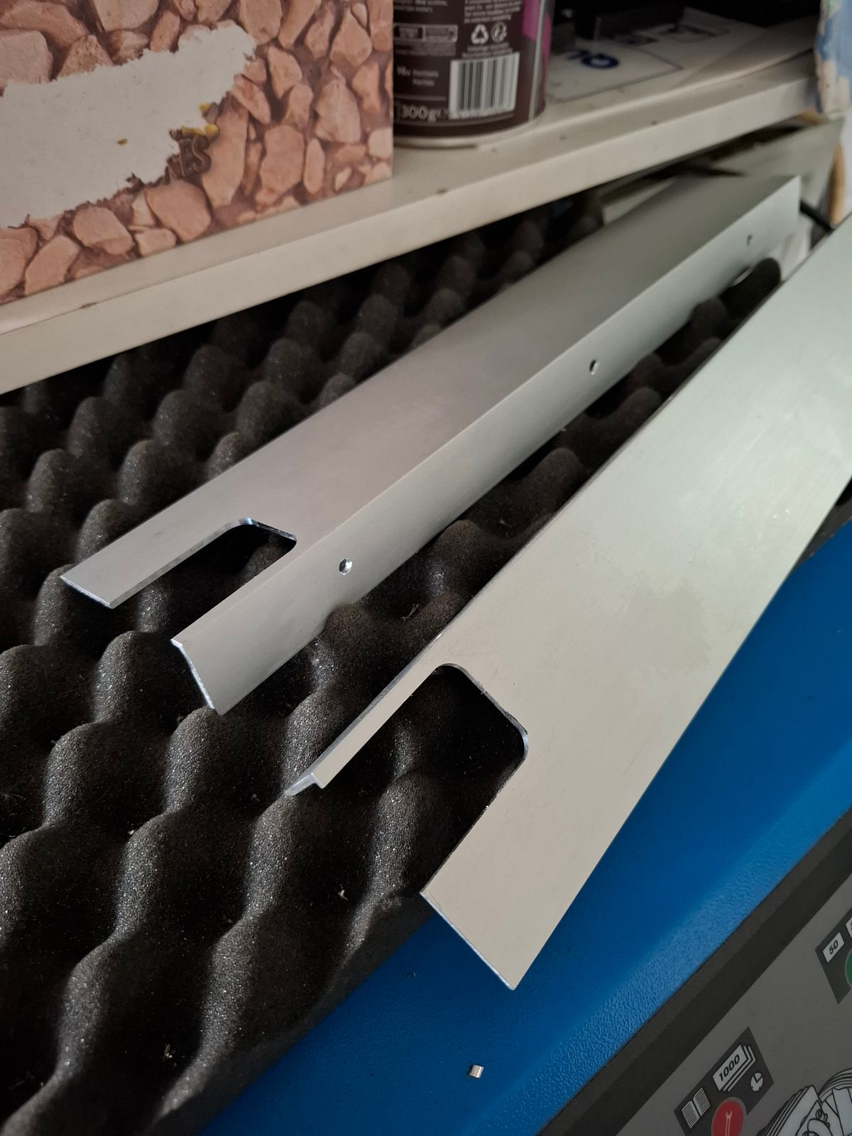
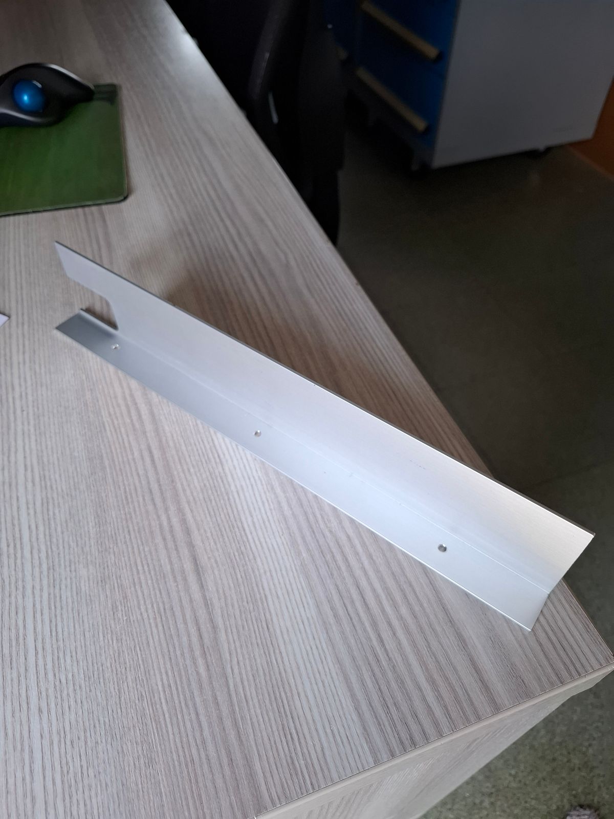
Alu profile for installation of the Align T Rex mechanics.
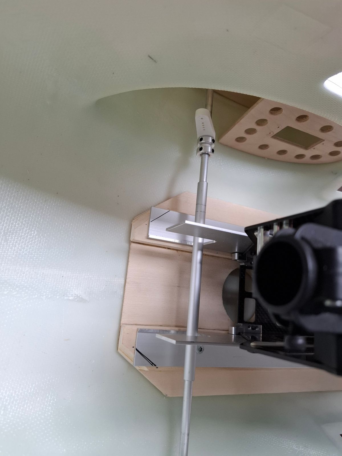
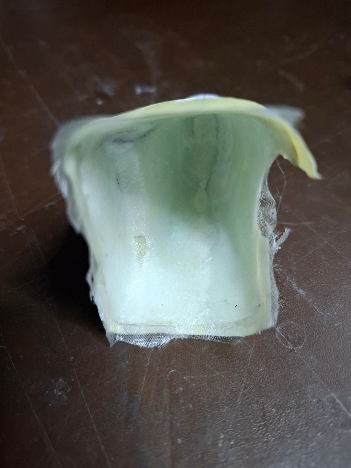
The landing gear retract problem story ...
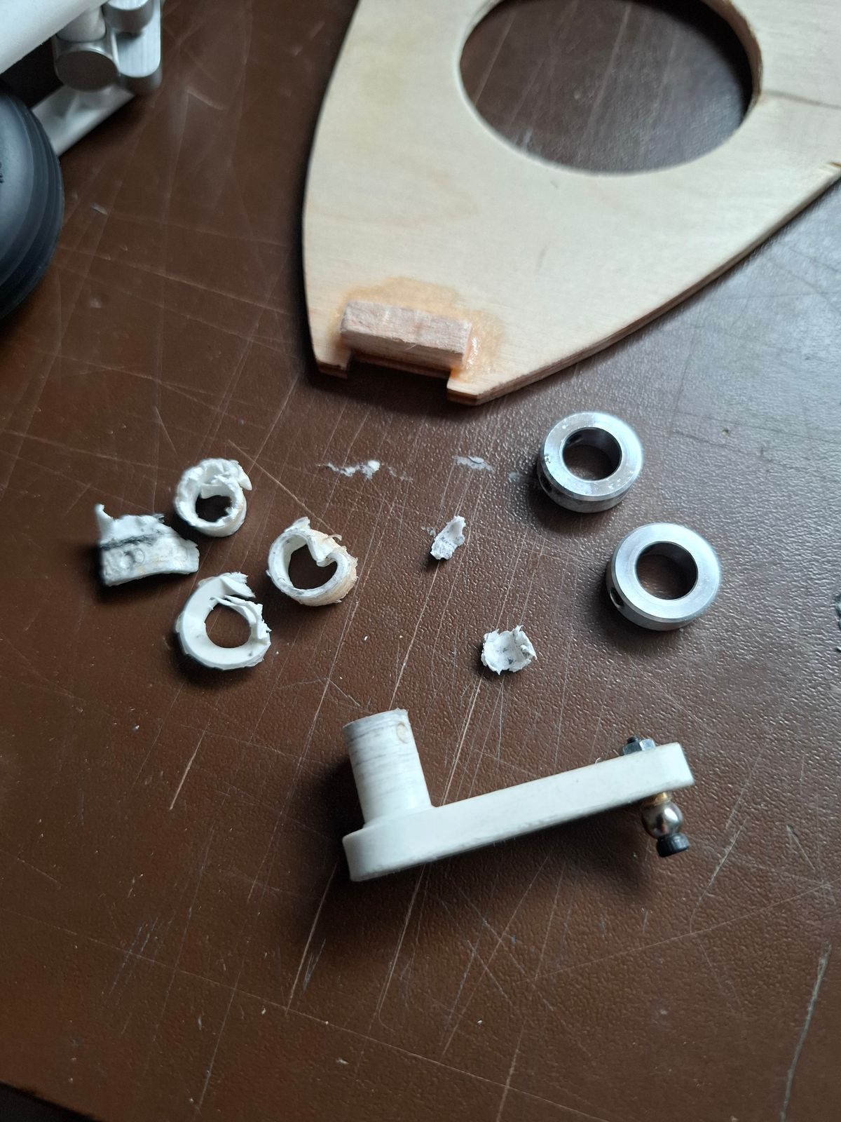
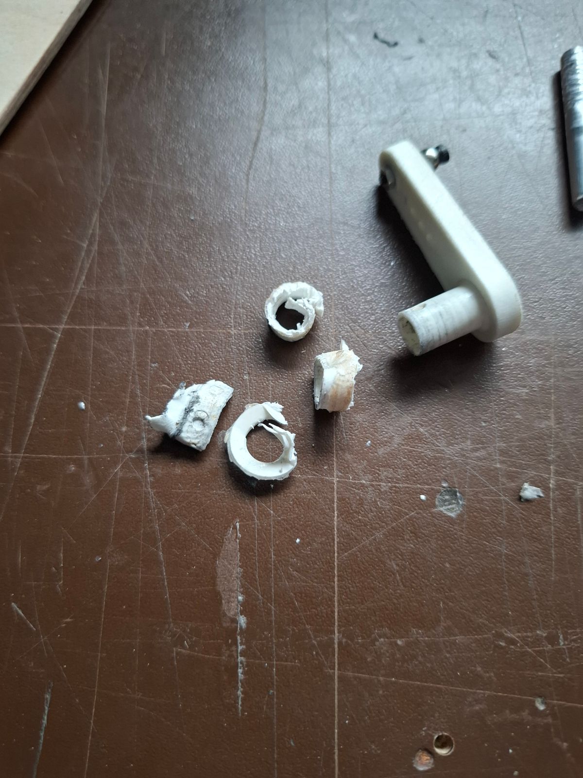
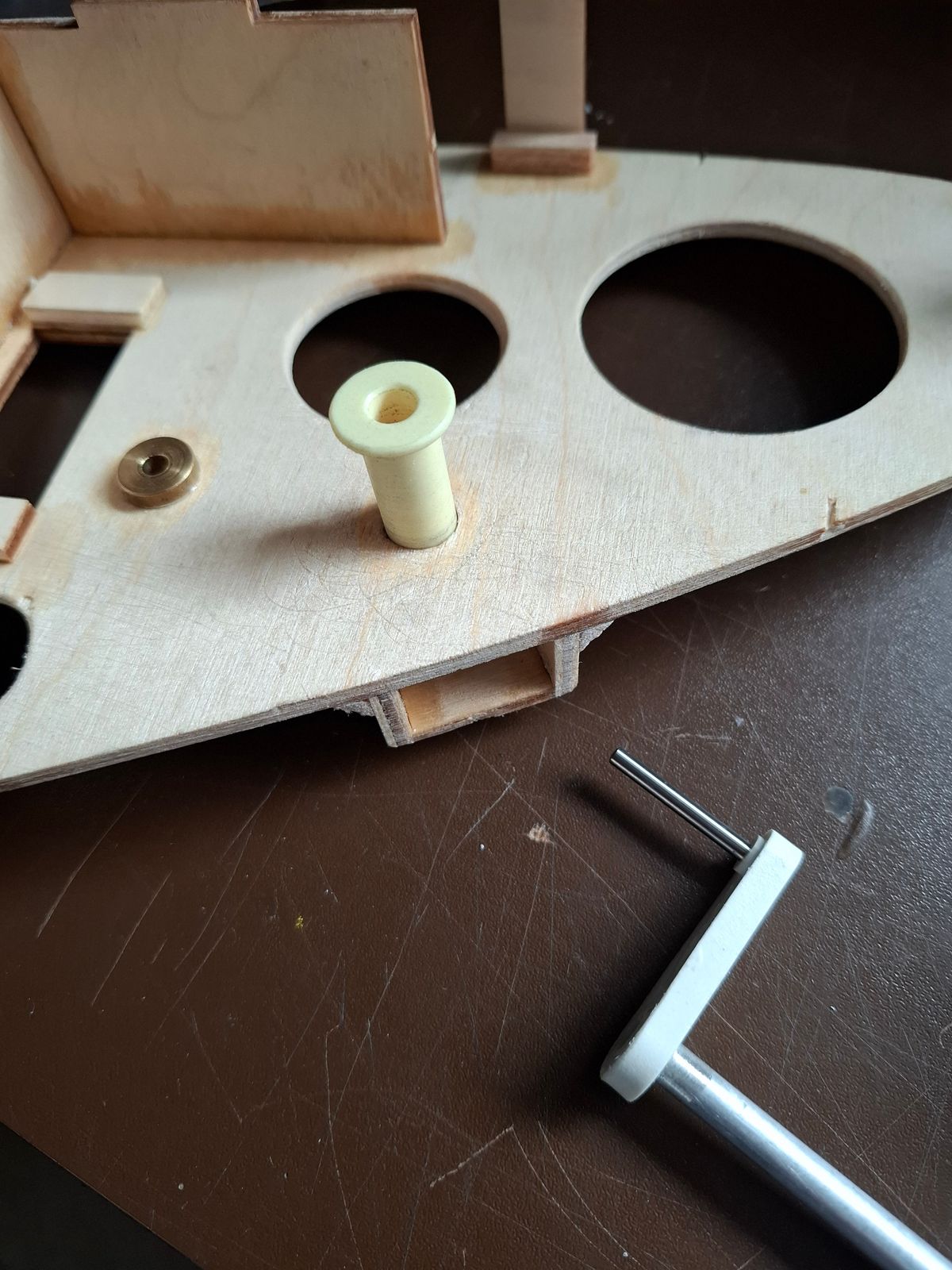
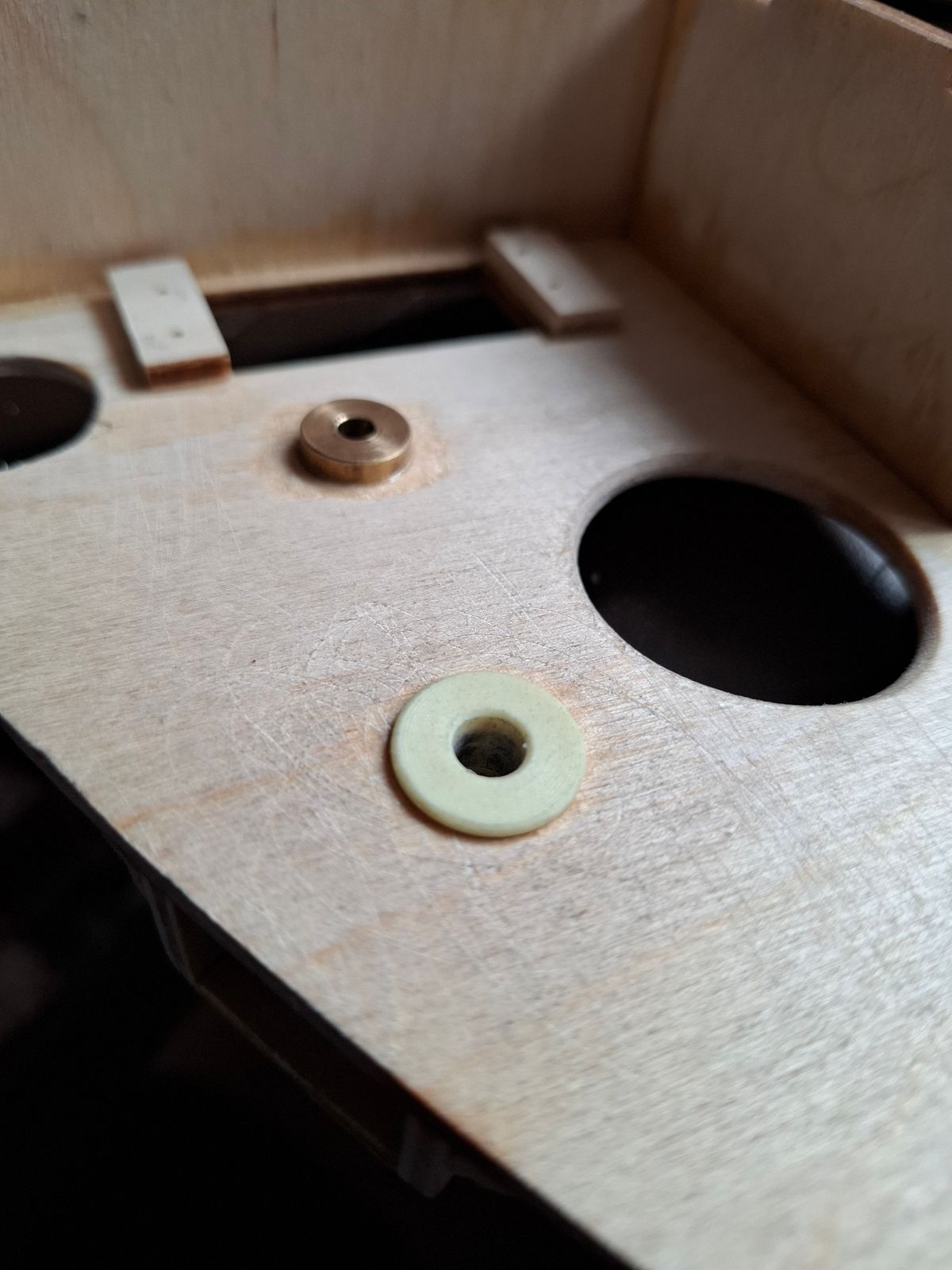
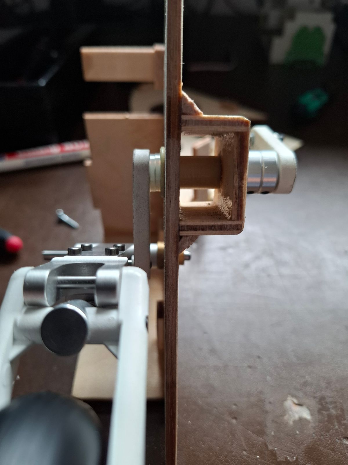
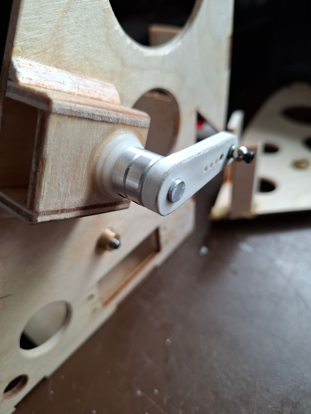
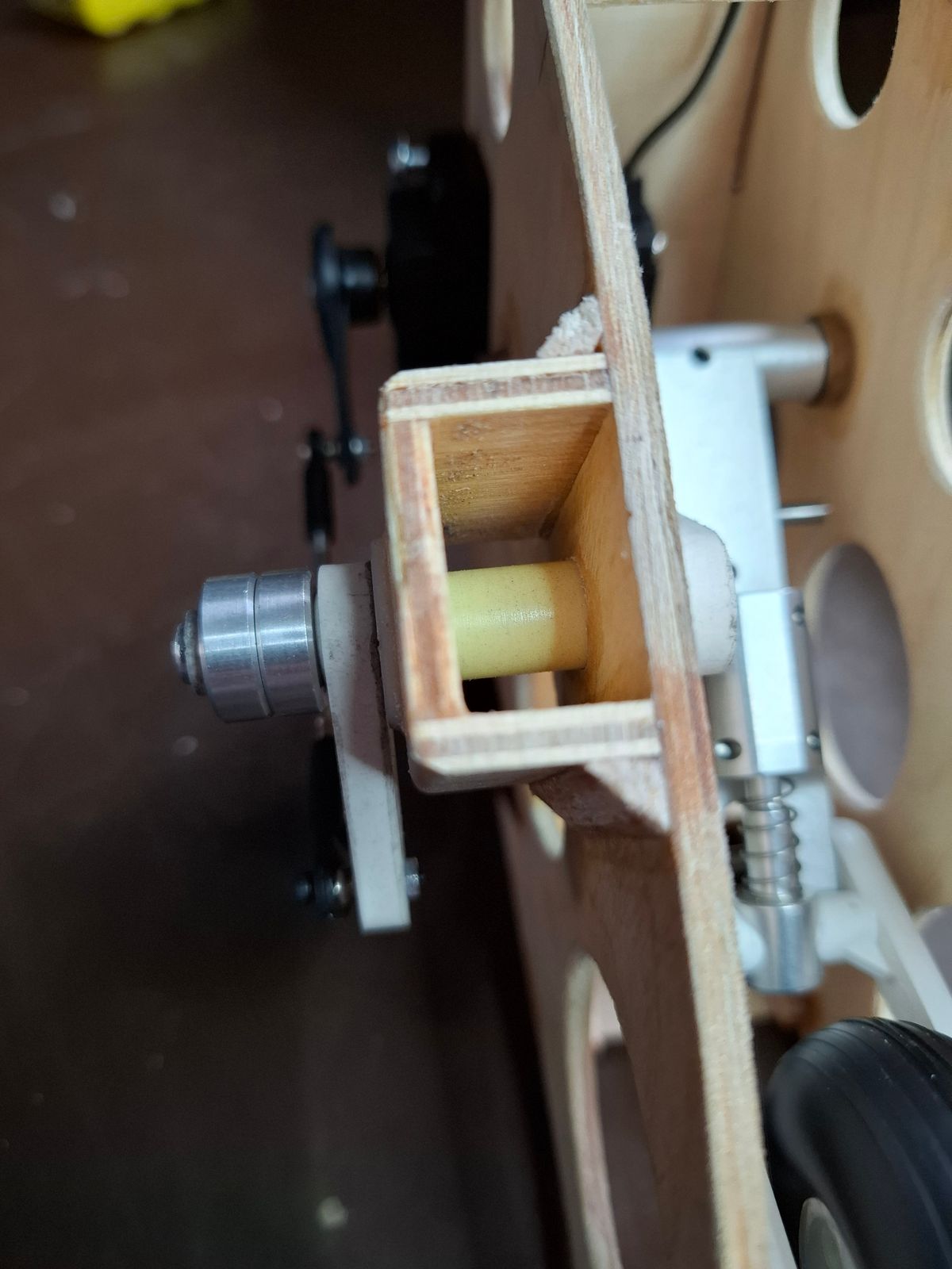
I had to rebuild the front gear mechanics due to bad kit parts.
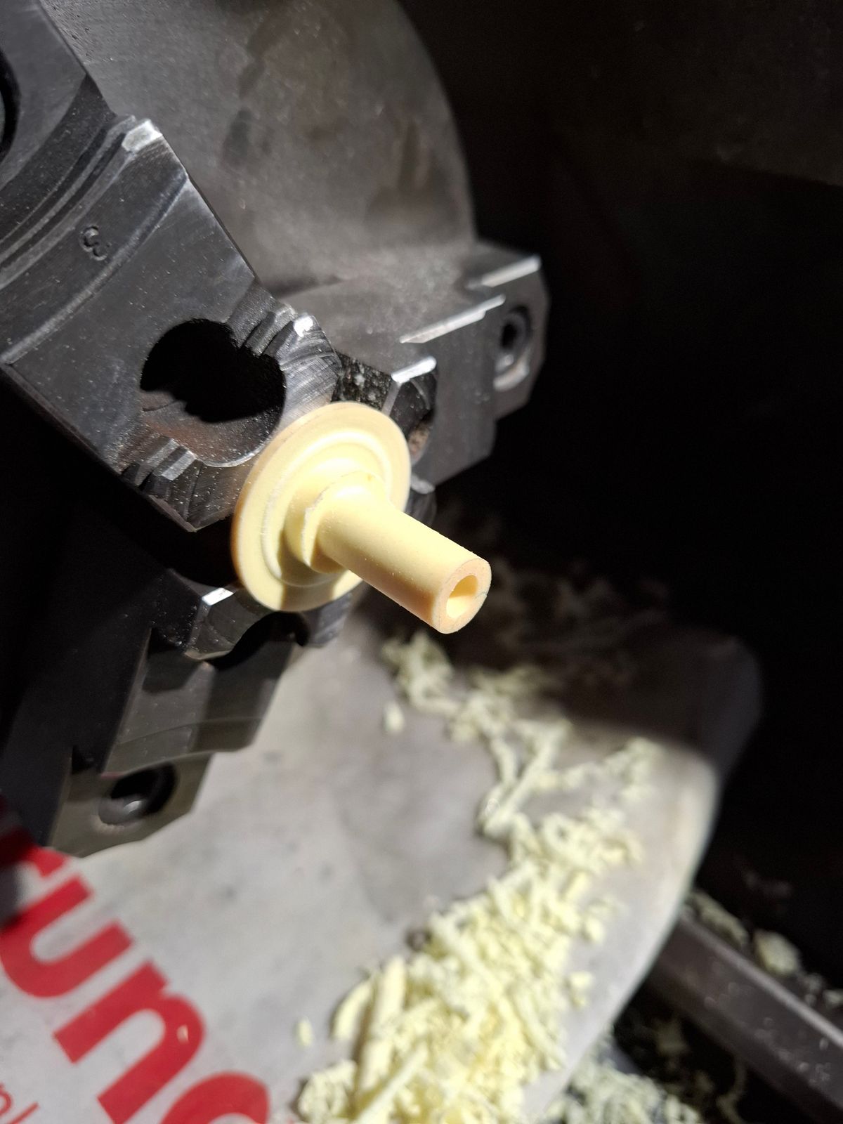
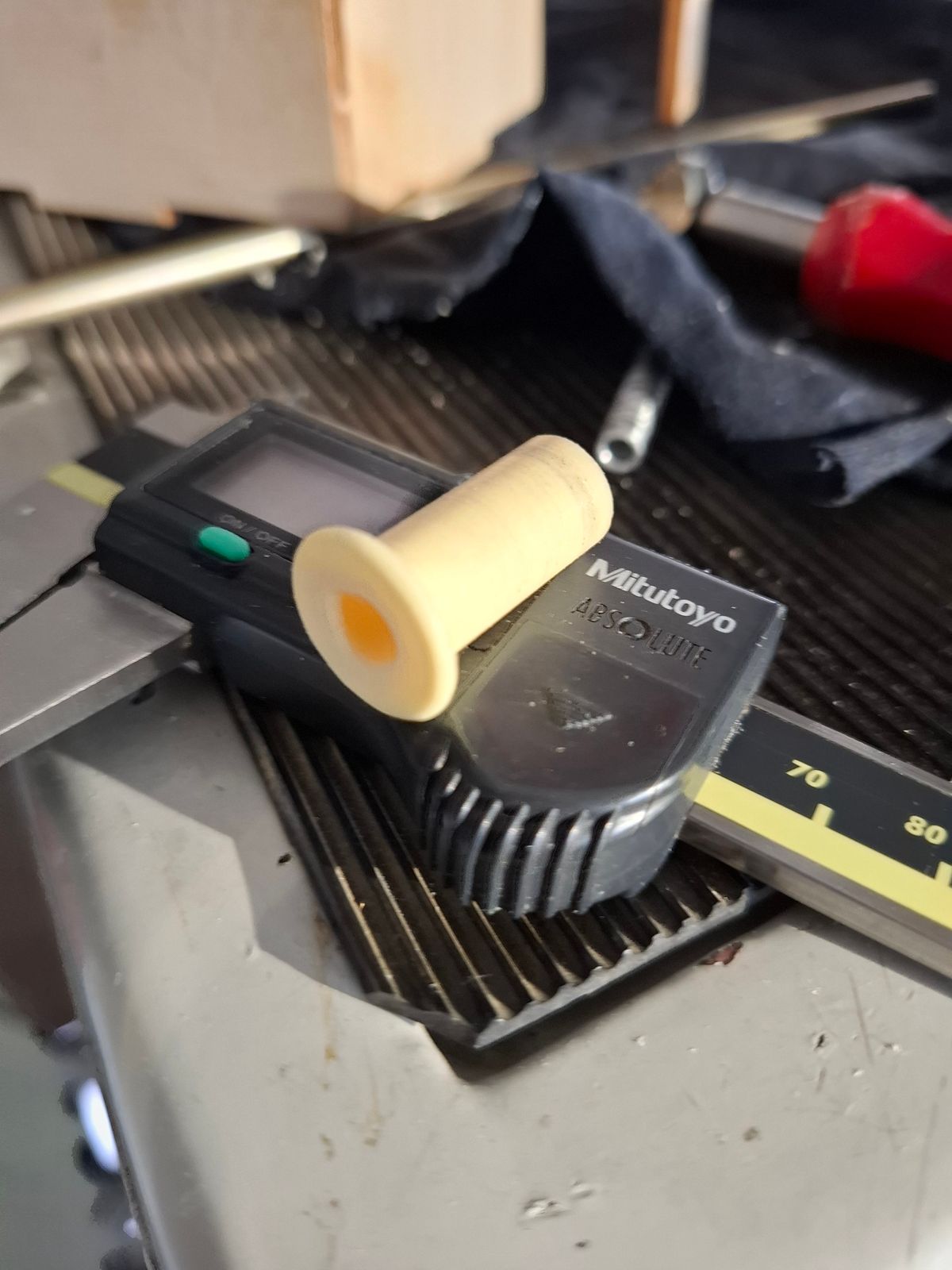
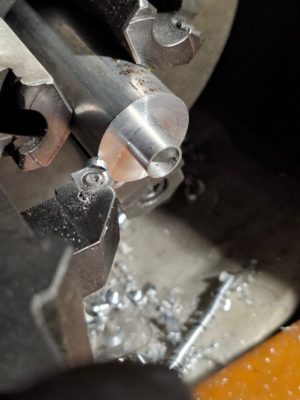
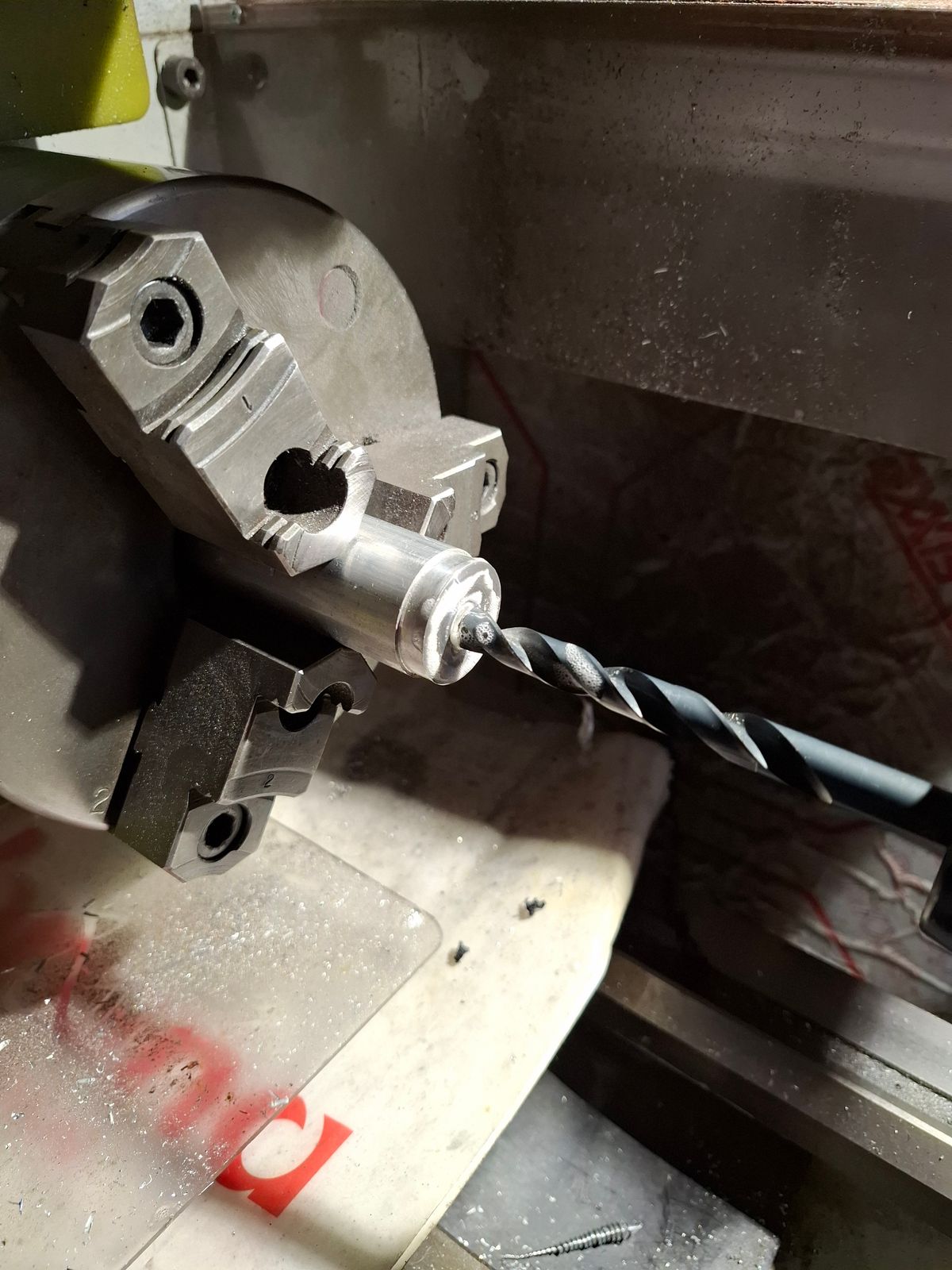
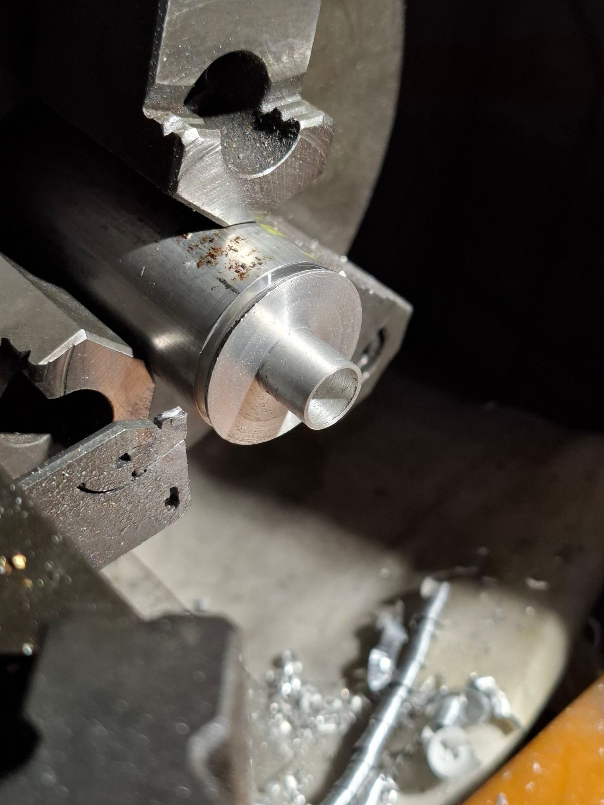
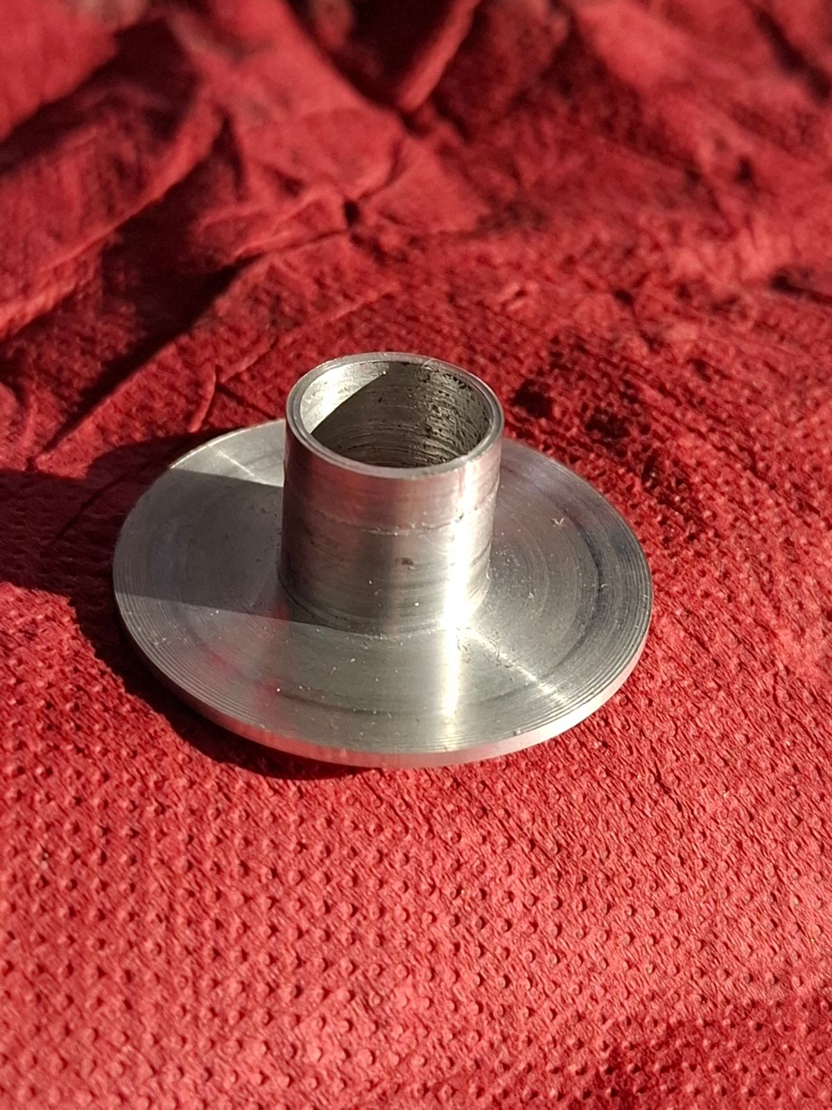
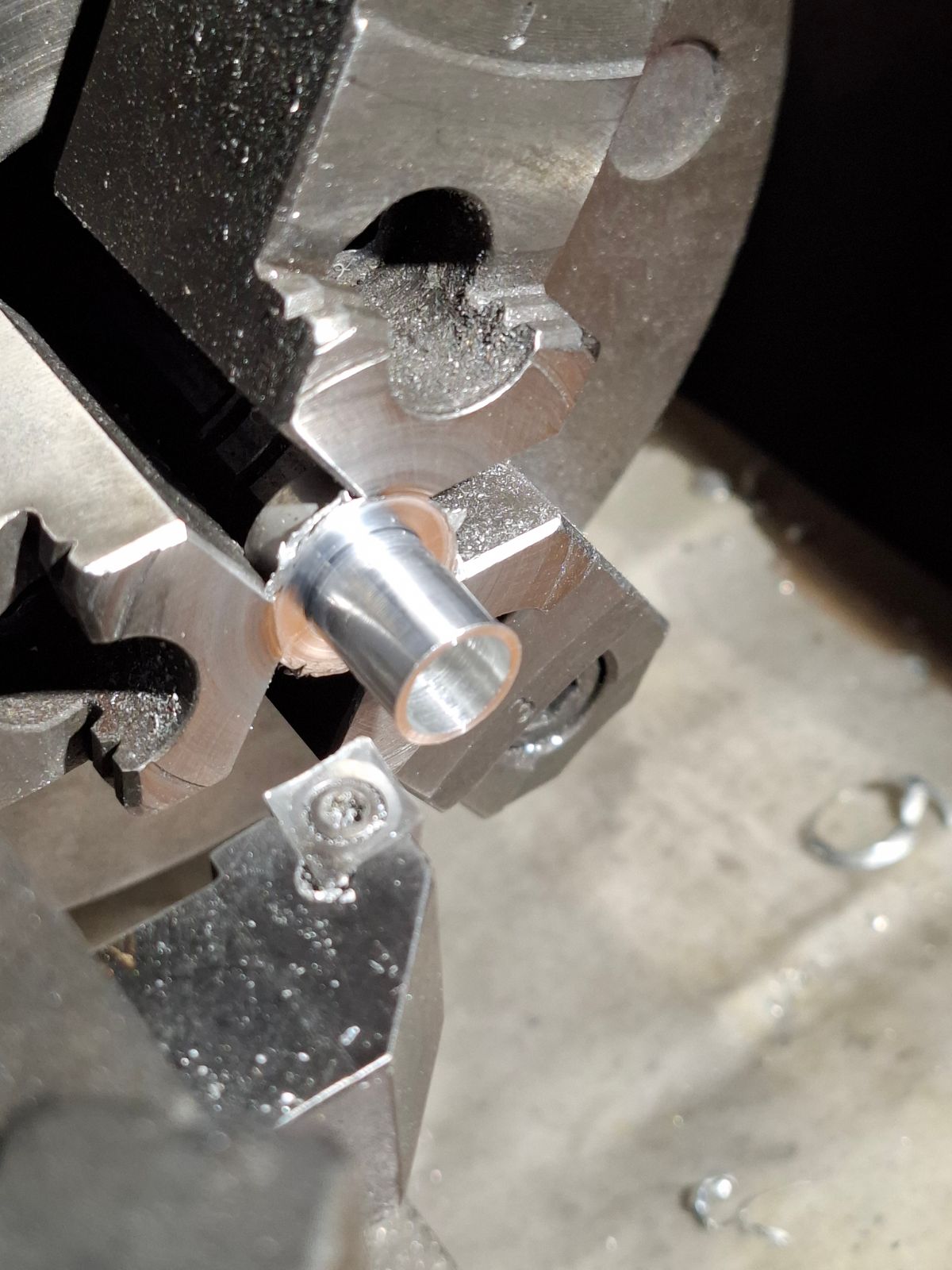
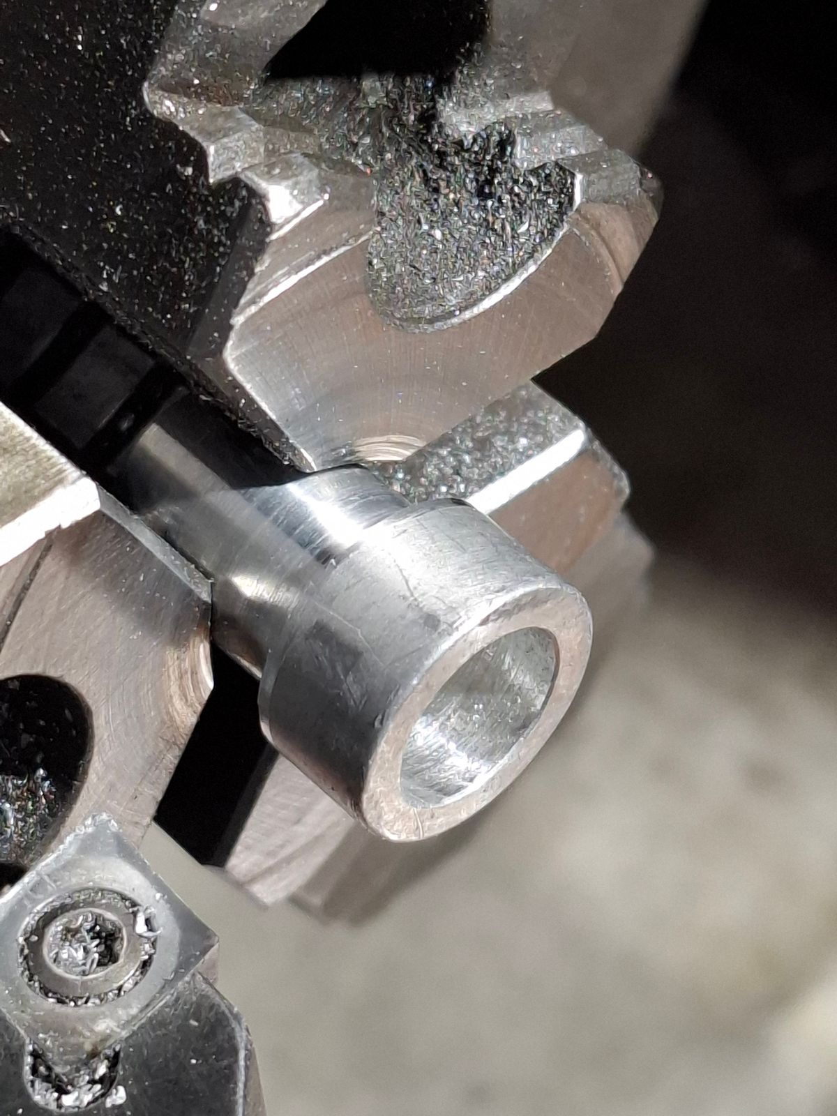
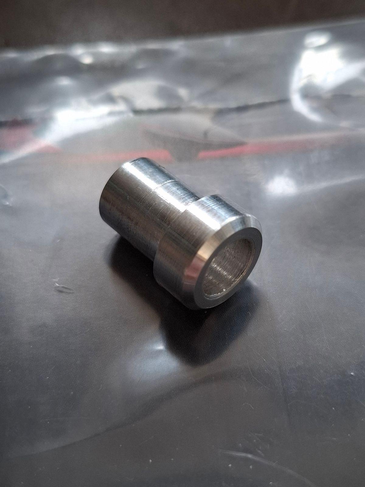
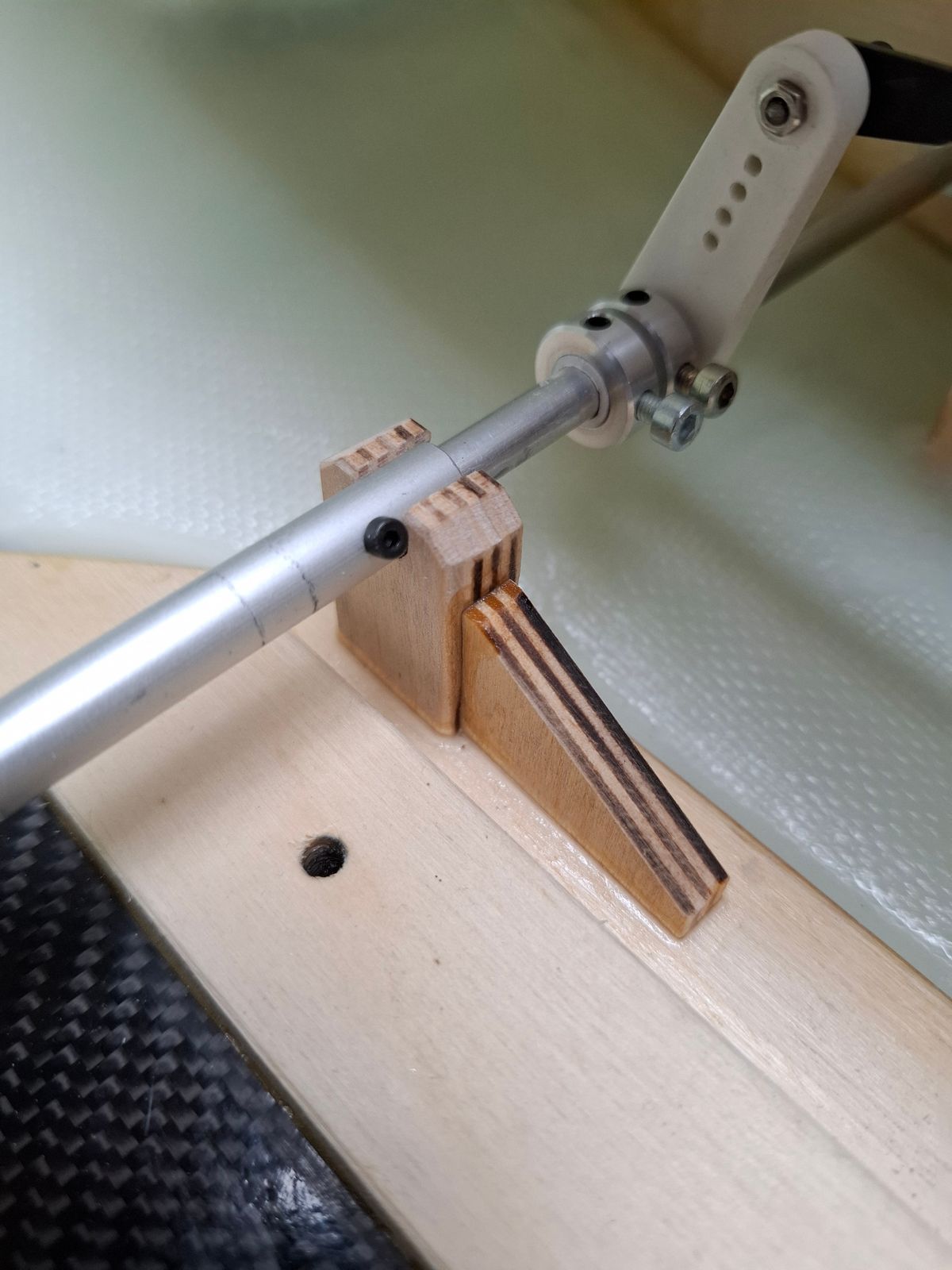
Turning new gear rotation shaft parts for a low friction operation.
The original parts glue'd up during rotation....
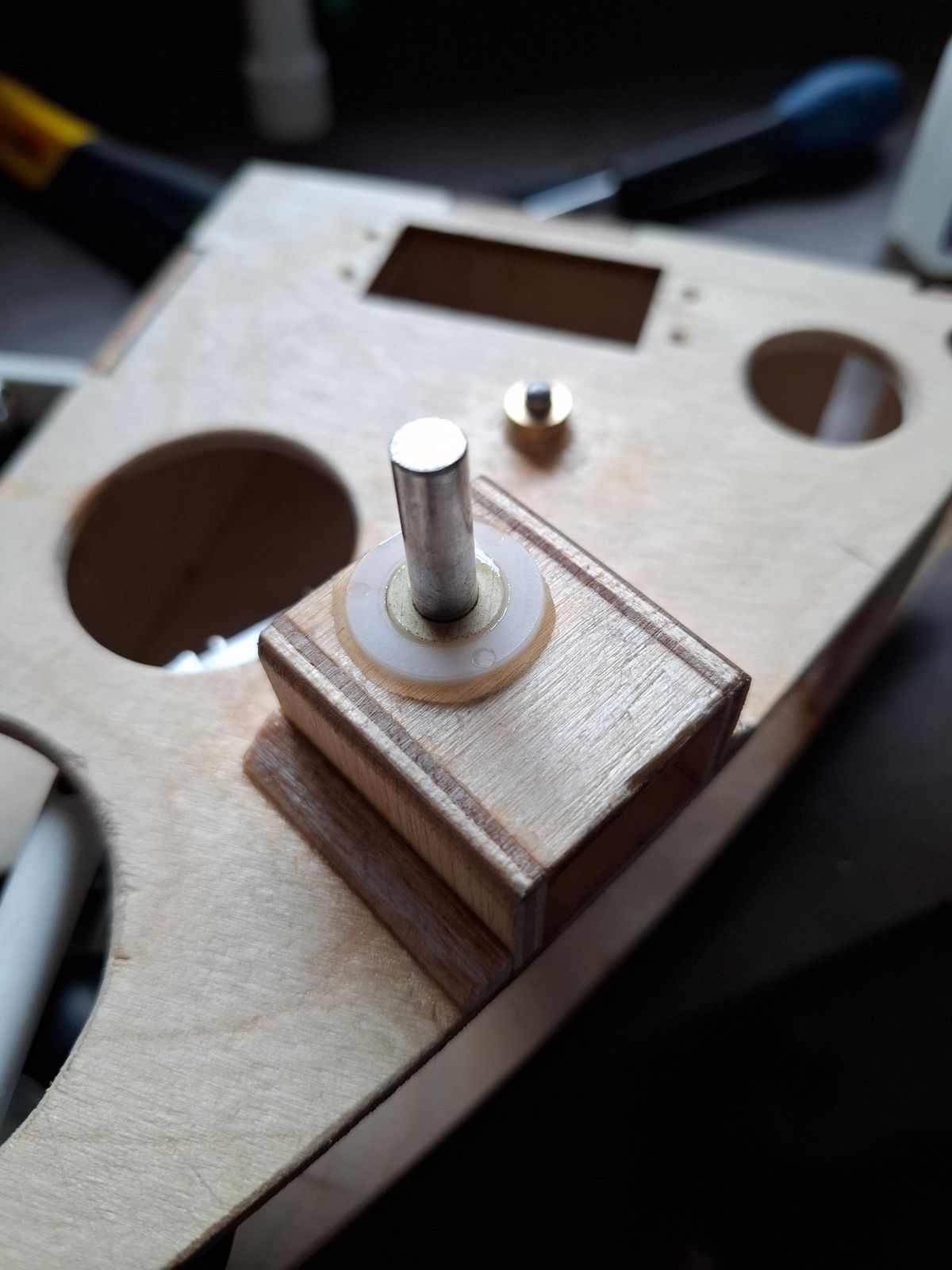
Solid aluminum shaft for better attachment to the drive servo arm.
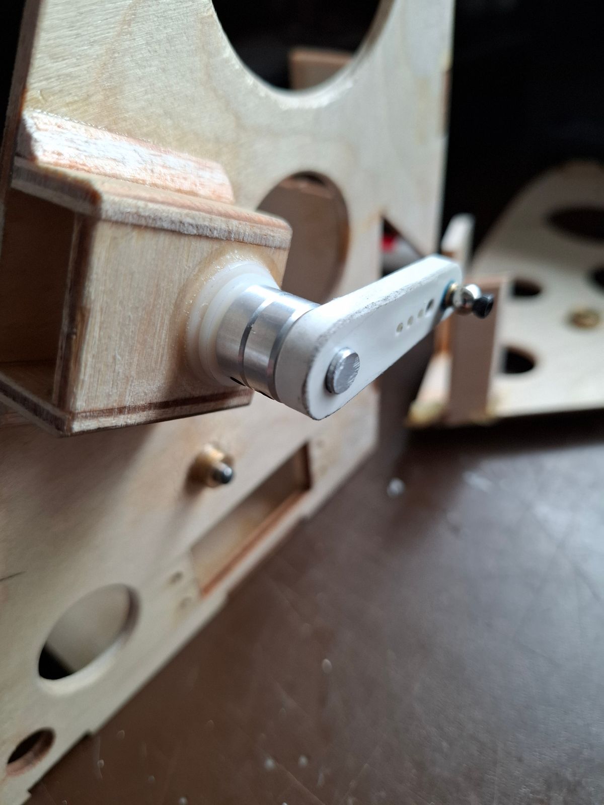
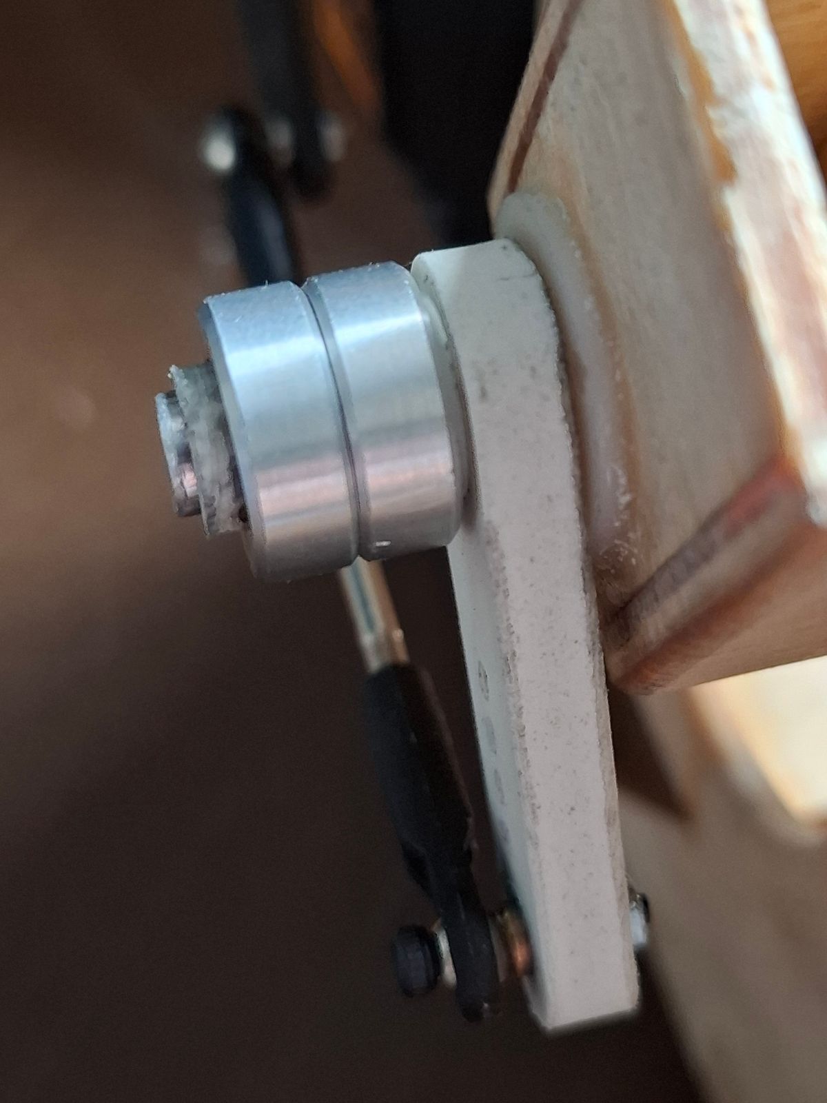
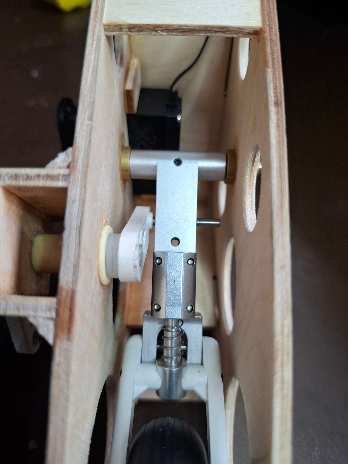
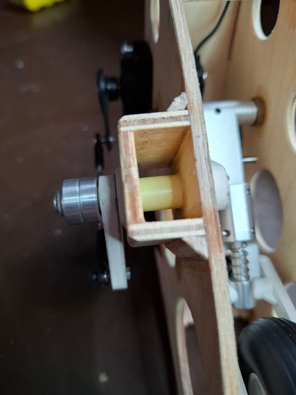
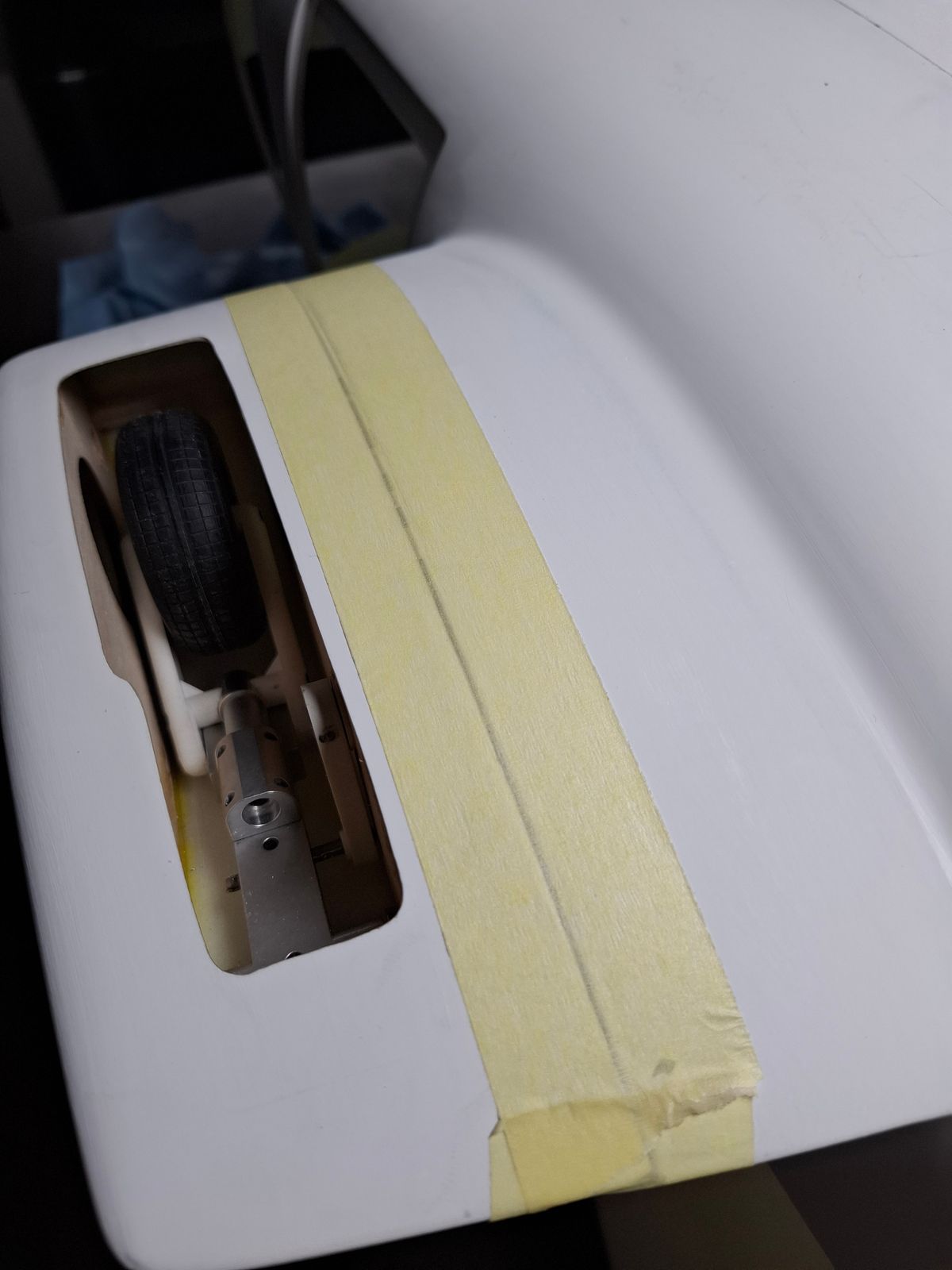
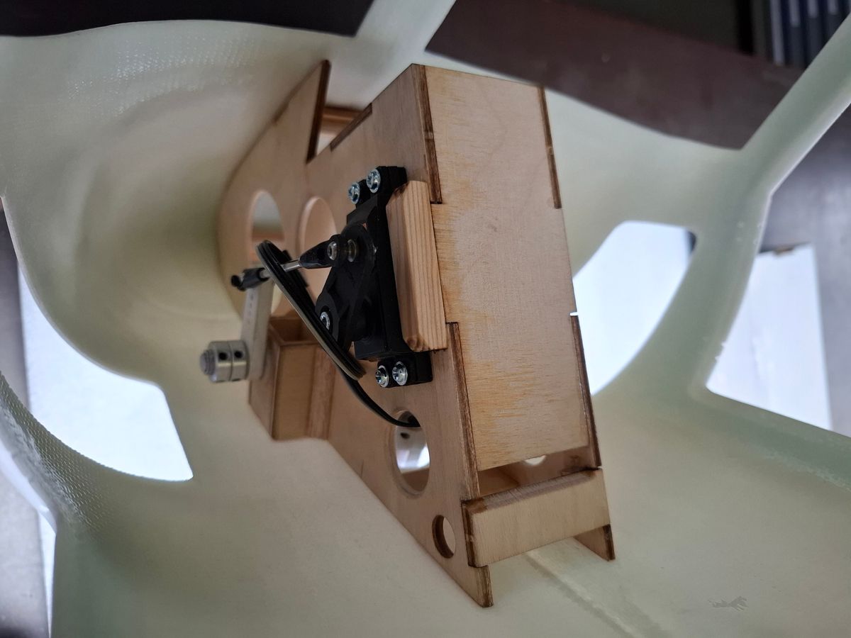
Retract mechanics laminating to the fuselage
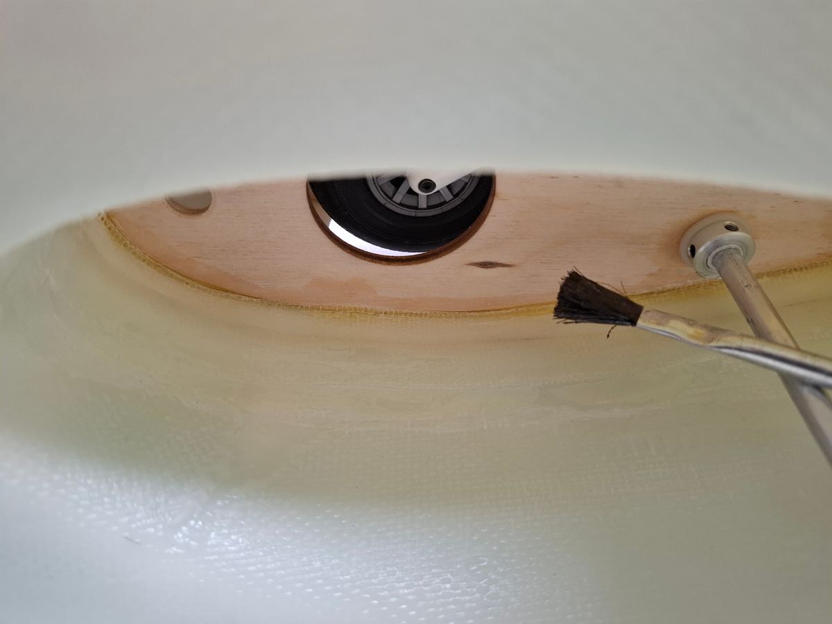
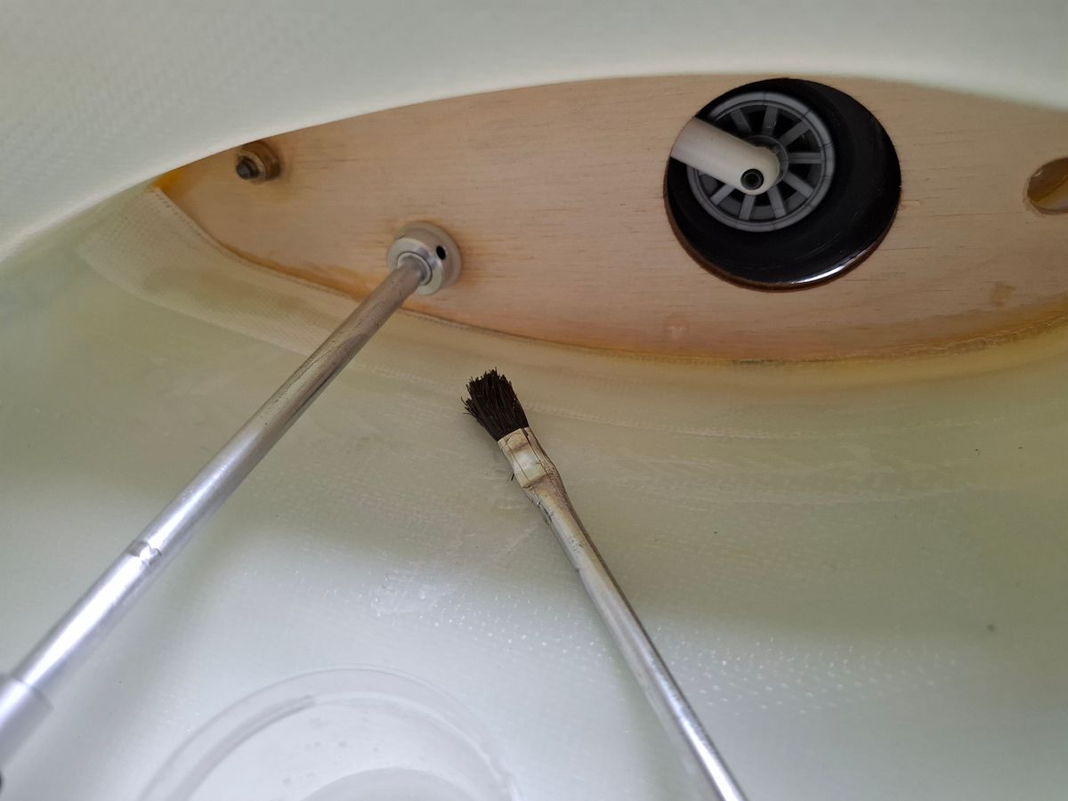
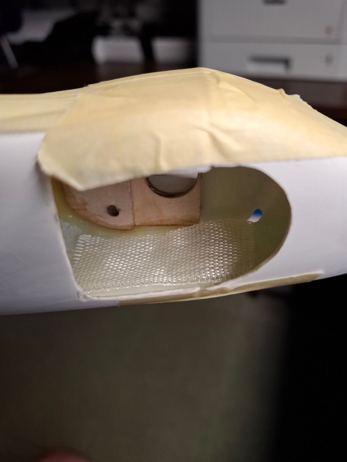
Laminating the retract mechanics to the fuselage.
It is not easy to line up all the wood parts in order to get a friction free operation.
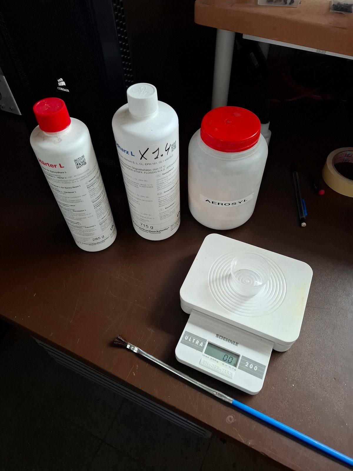
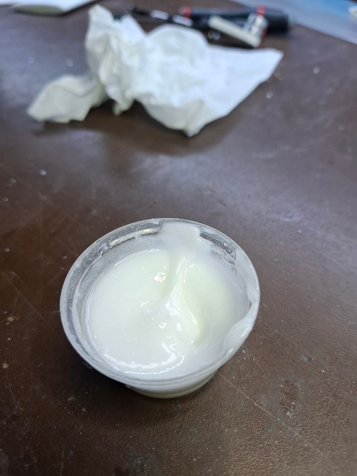
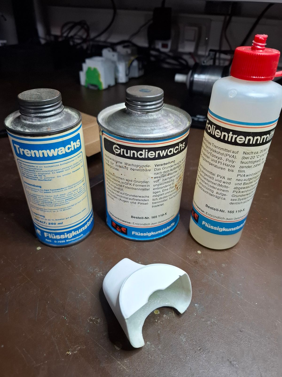
Laminating glue is R&G L 40 min potlife with some Aerosil to make it less liquid.
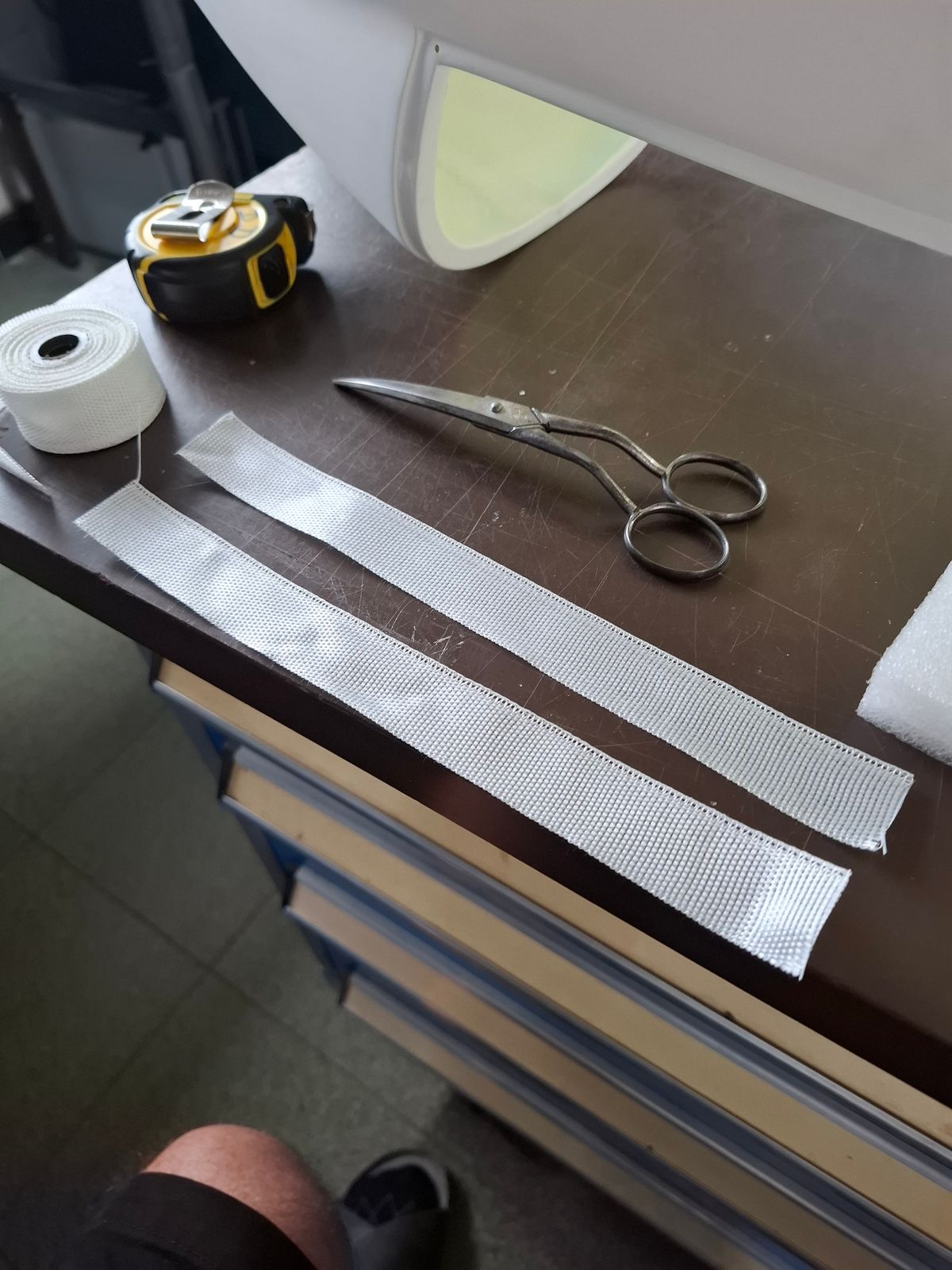
The wings are reinforced with a glasfiber tape for additional strength to the fuselage.
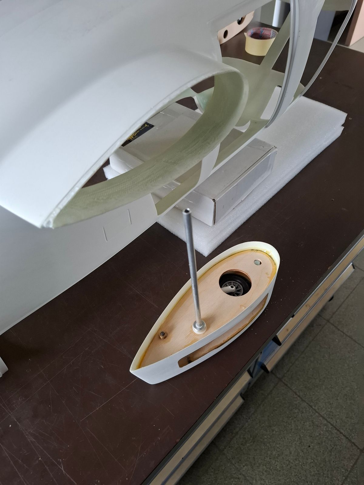
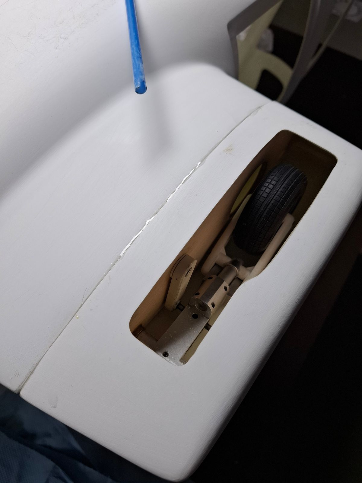
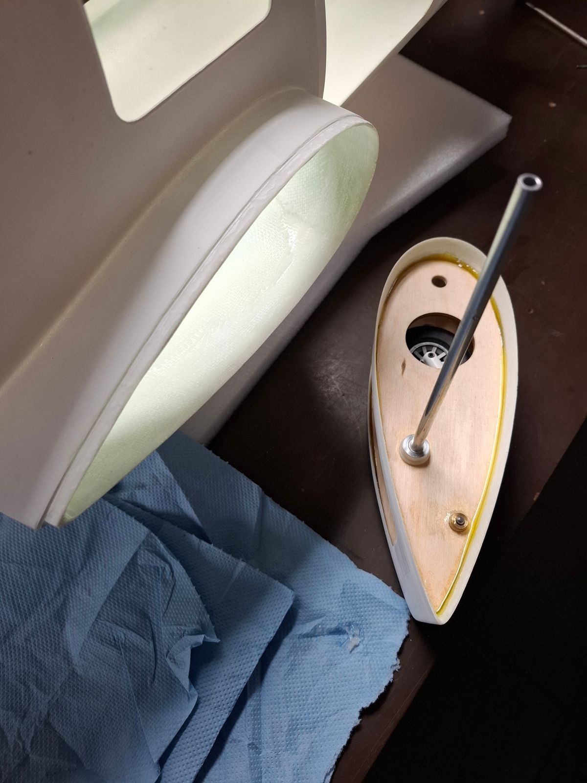
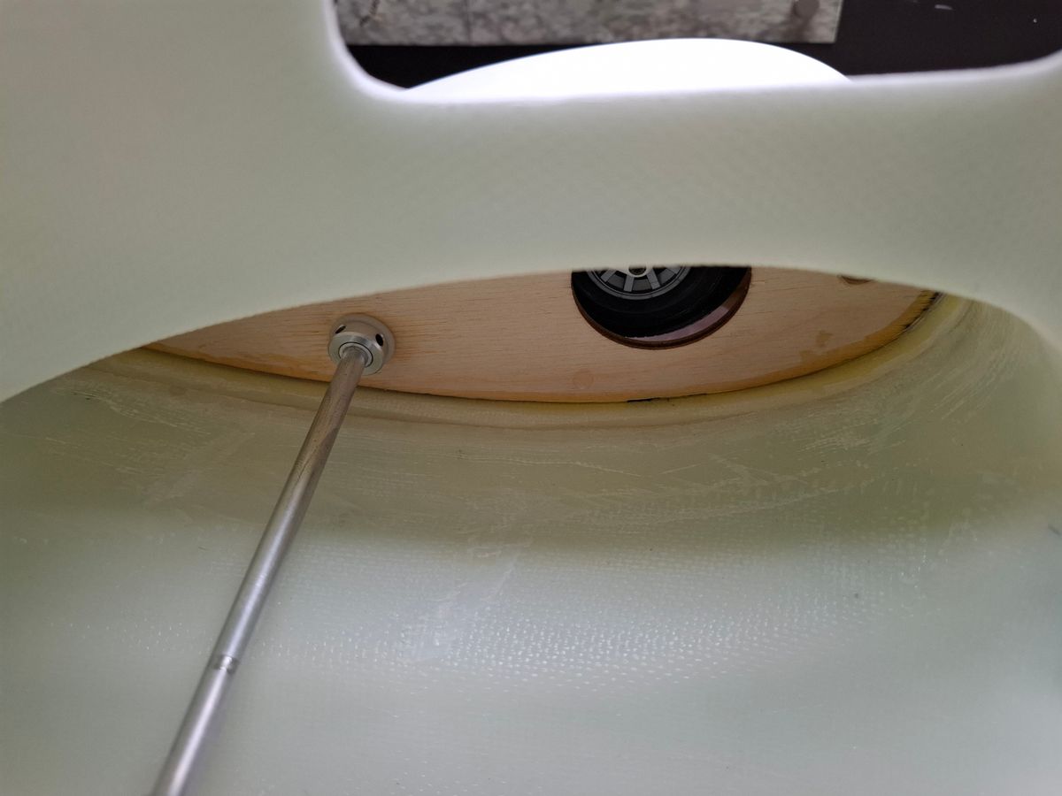
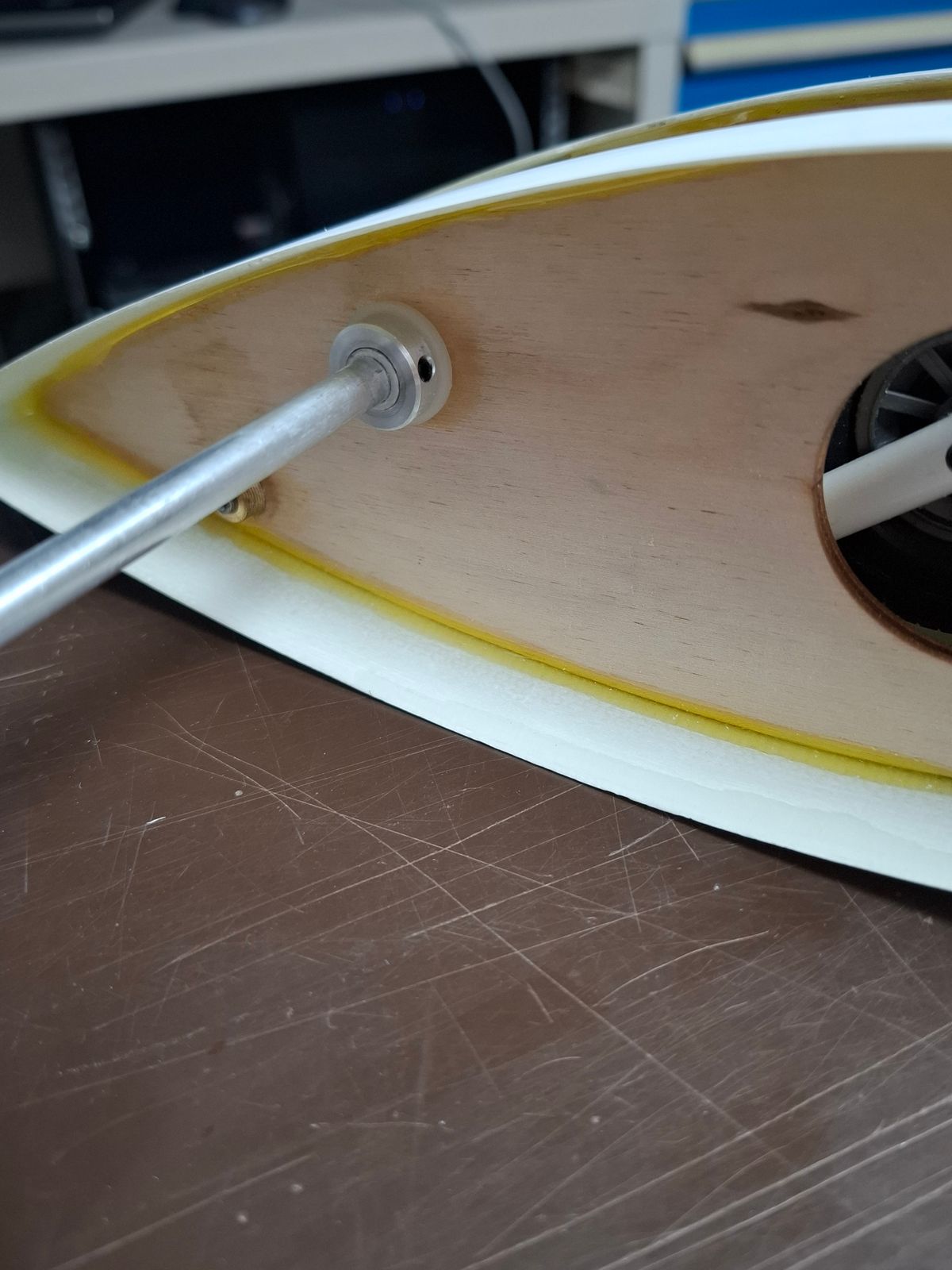
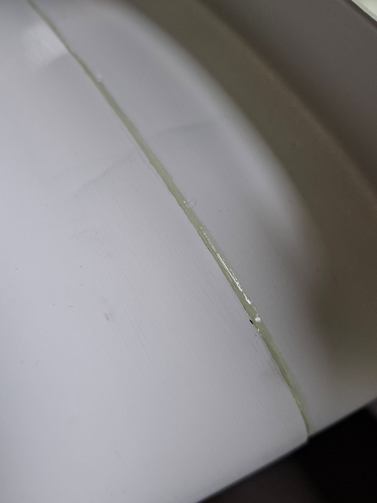
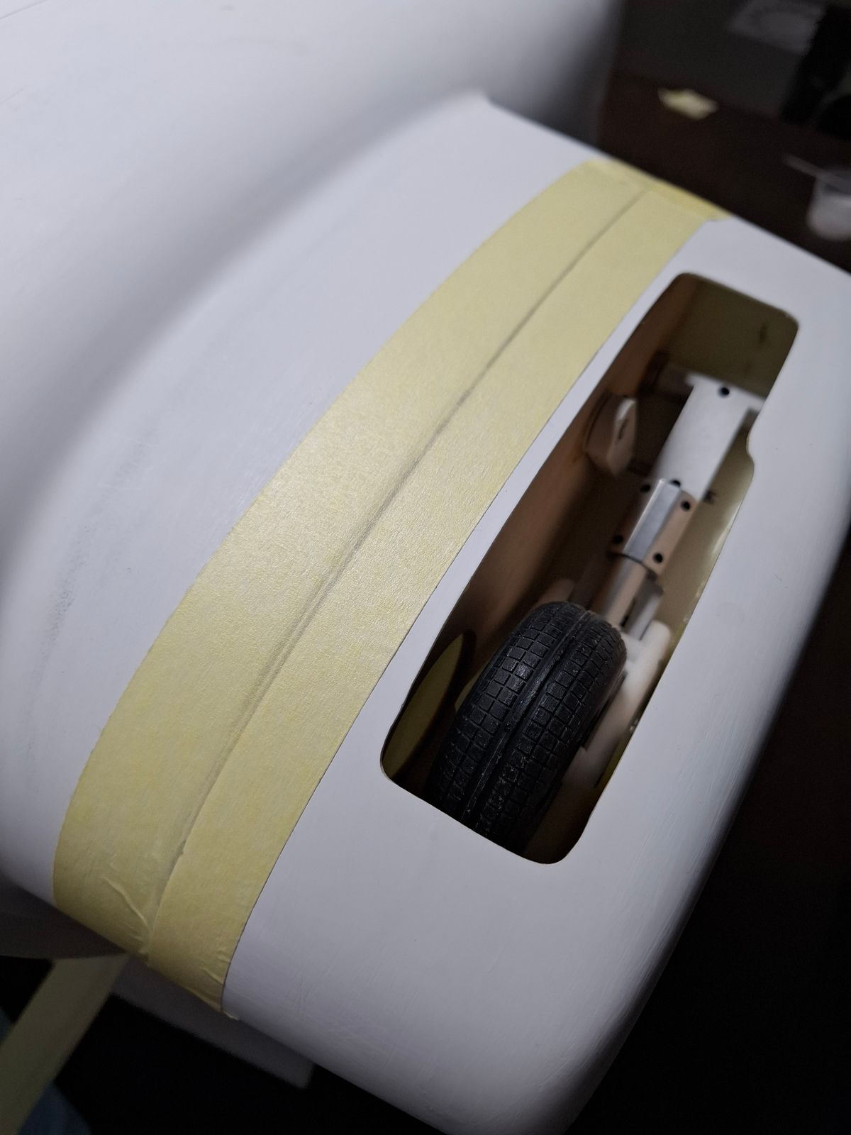
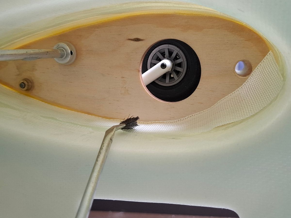
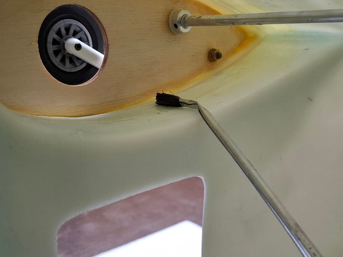
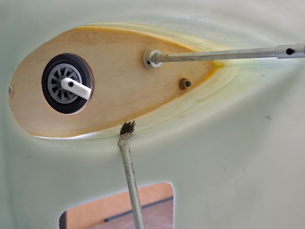
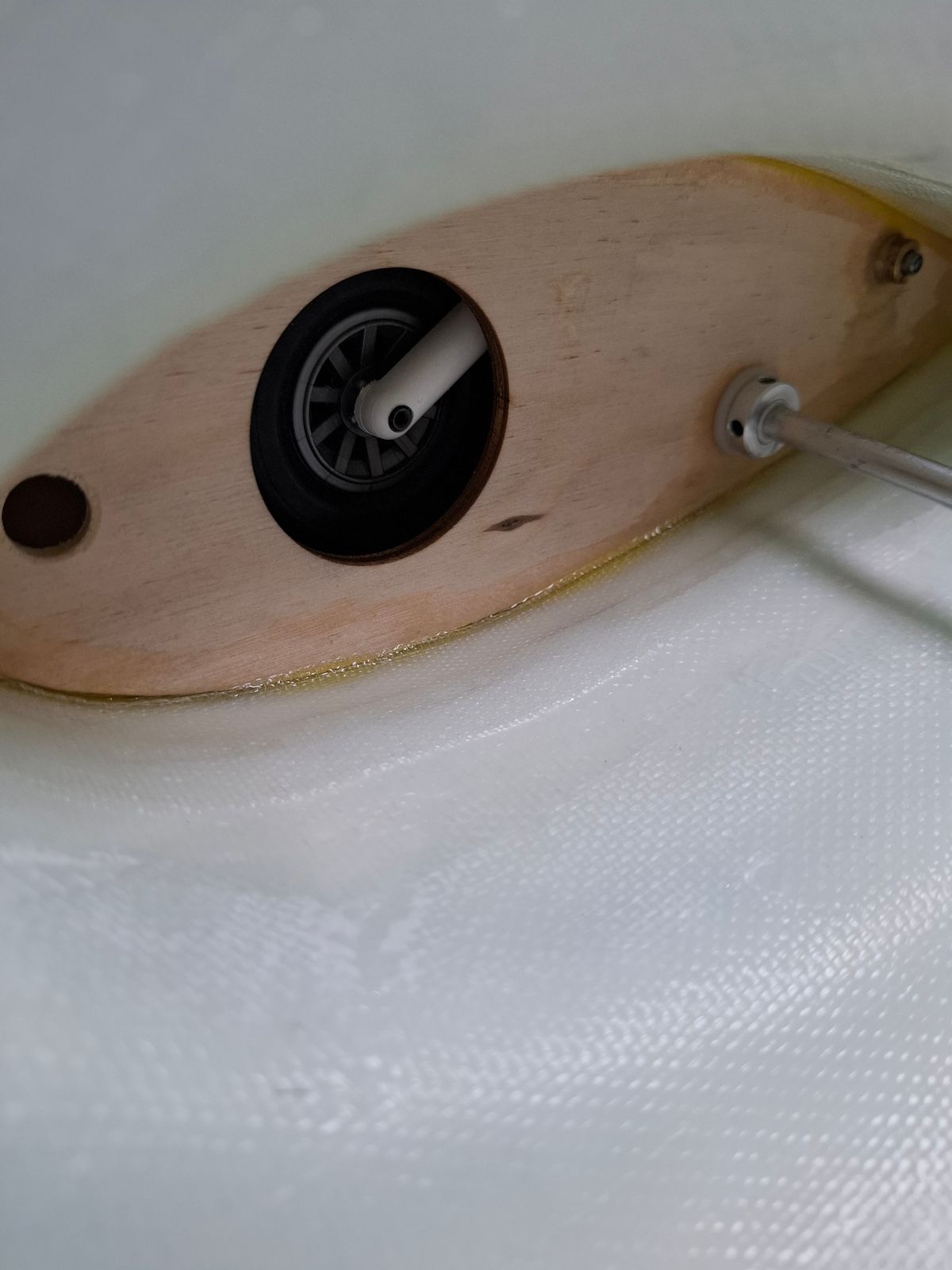
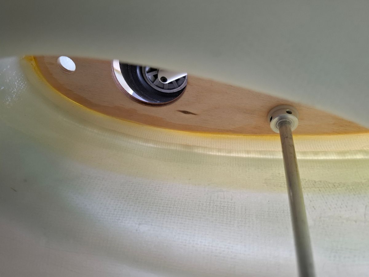
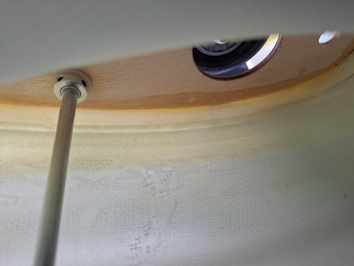
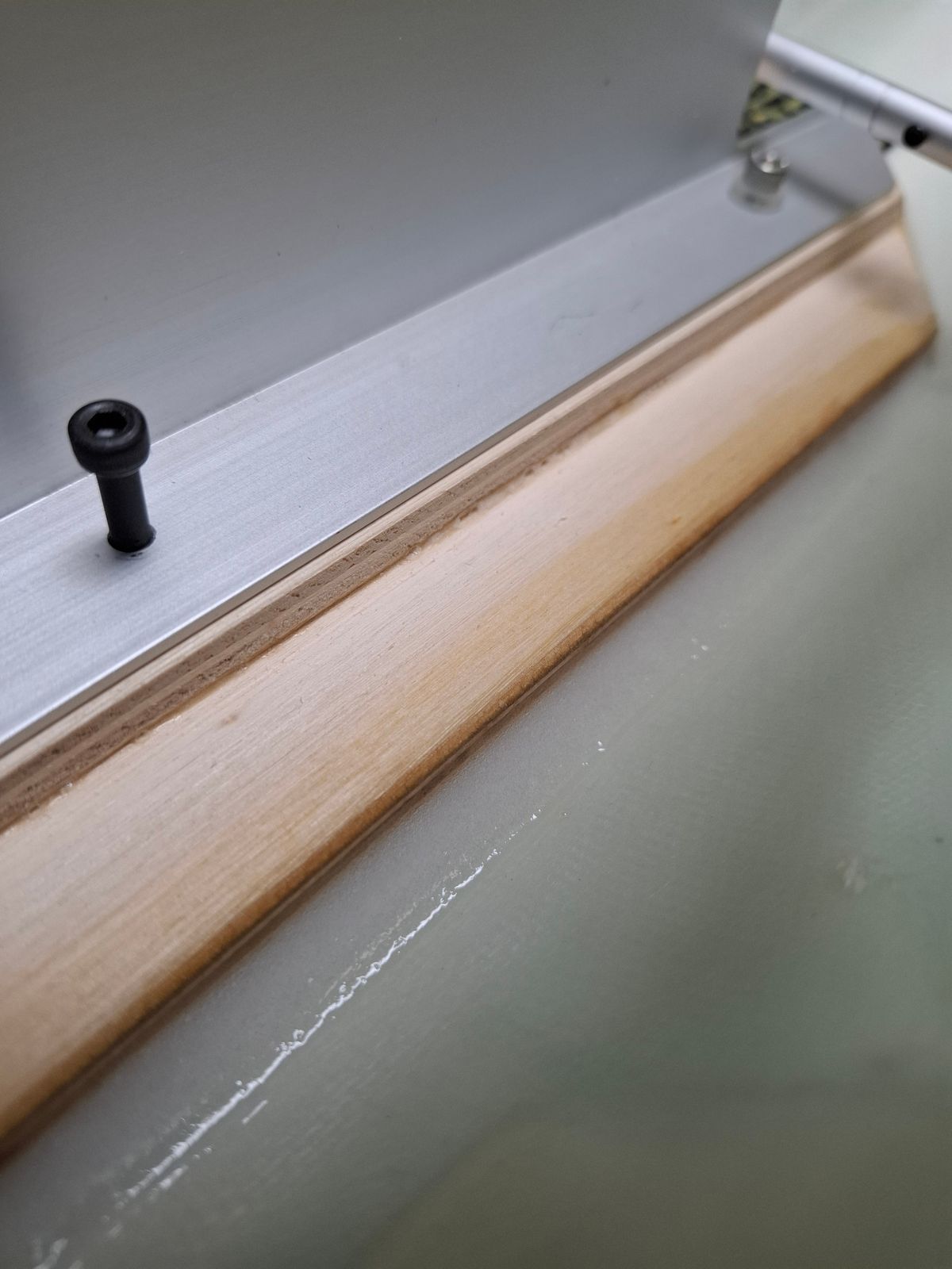
Baseframe glueing to the fuselage.
Glue the wooden baseframe to the fuselage.
Reinforce the front side retract with carbon kevlar layer.
Sides of wood base plate edge filled with epoxy / Aerosil mixture, in order to get a nice filling paste.
This way you get nice clean joint.
Mid section closed with a 0.3mm carbon layer
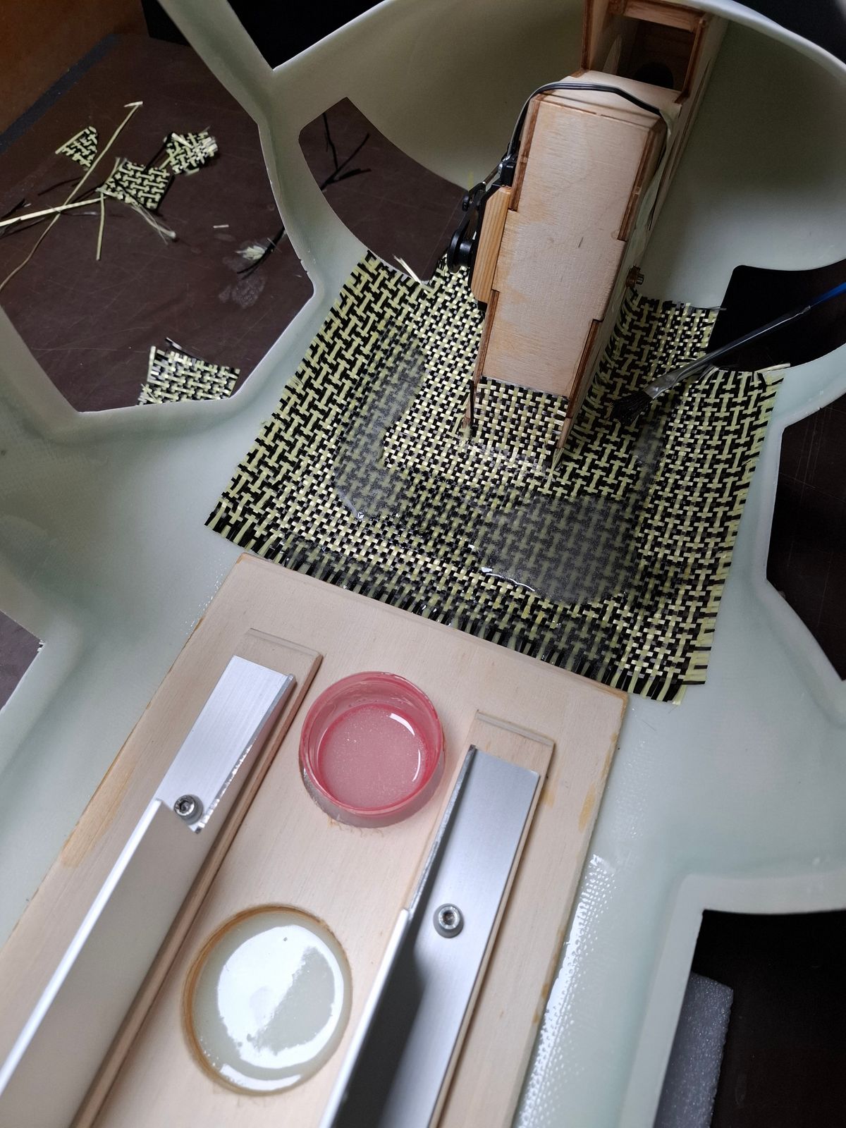
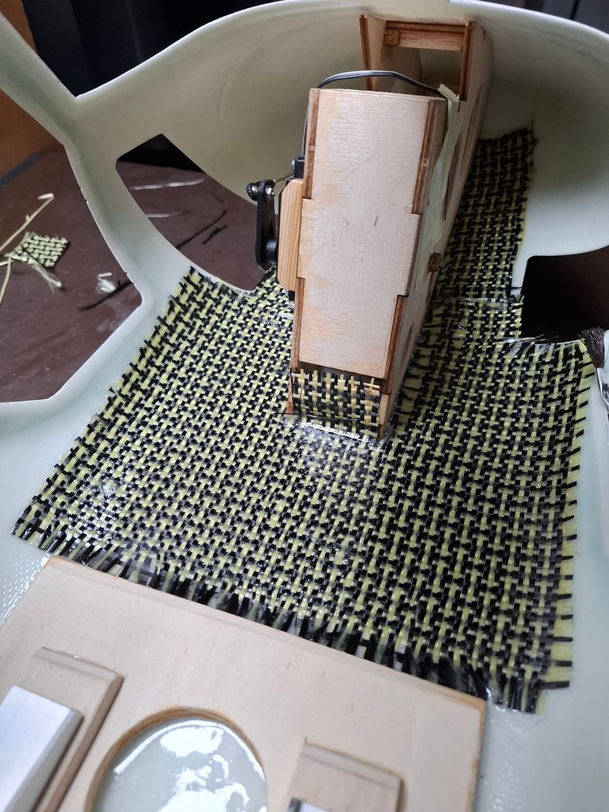
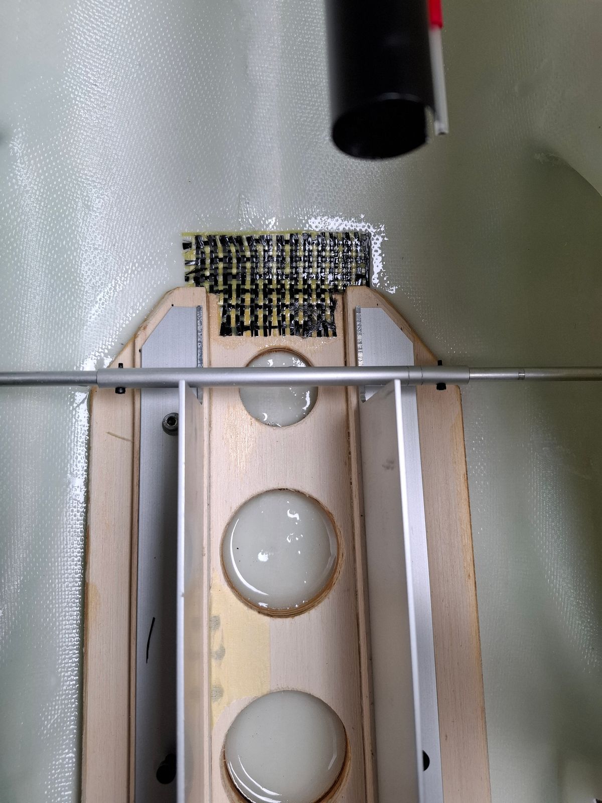
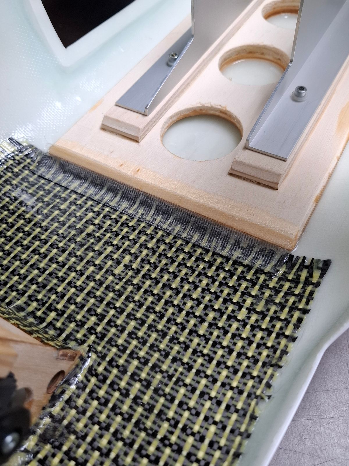
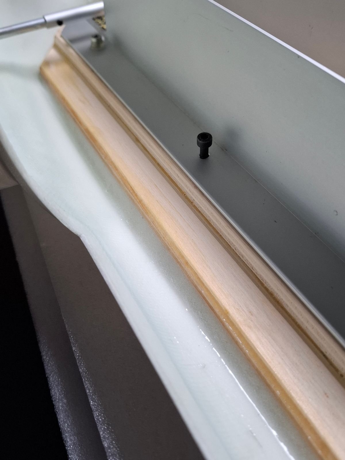
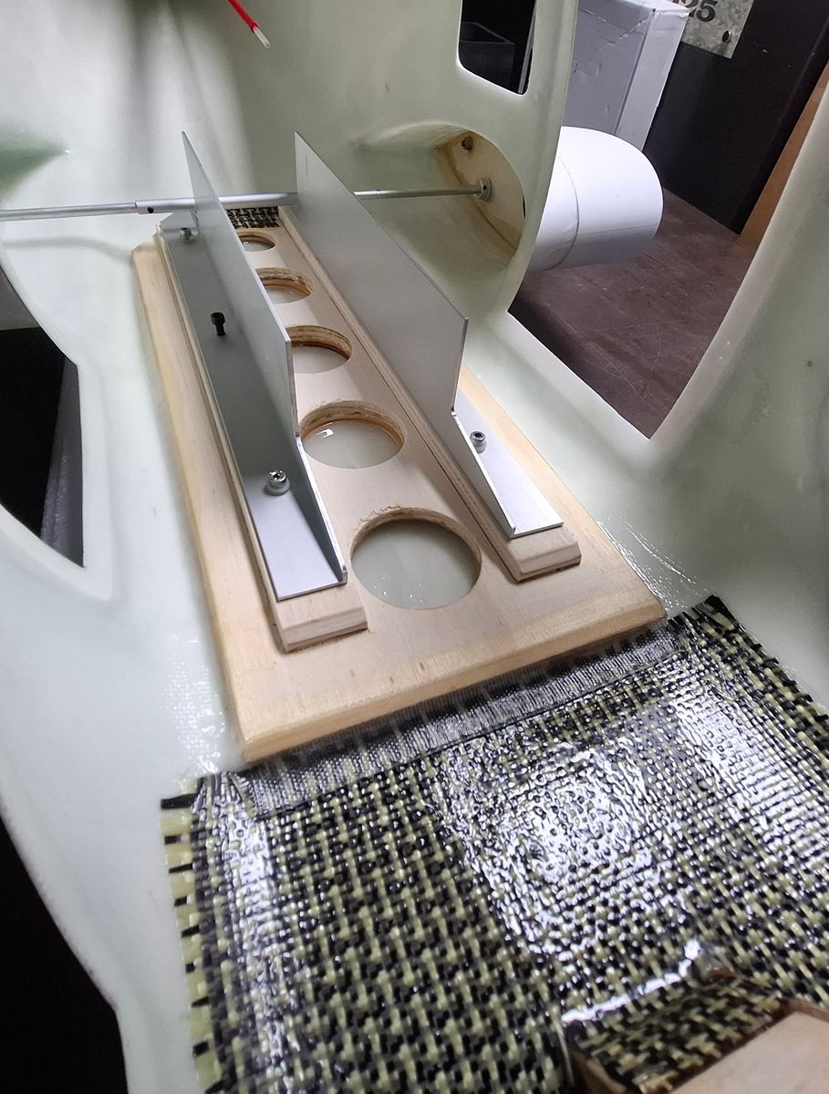
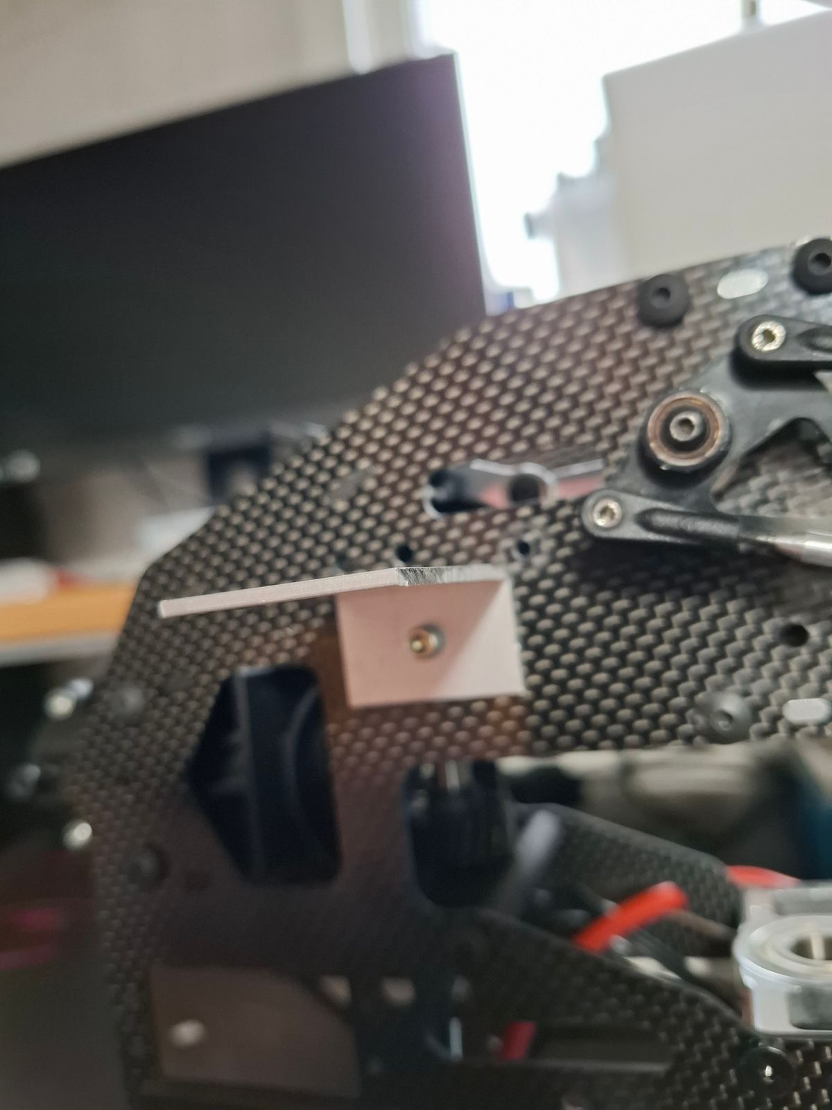
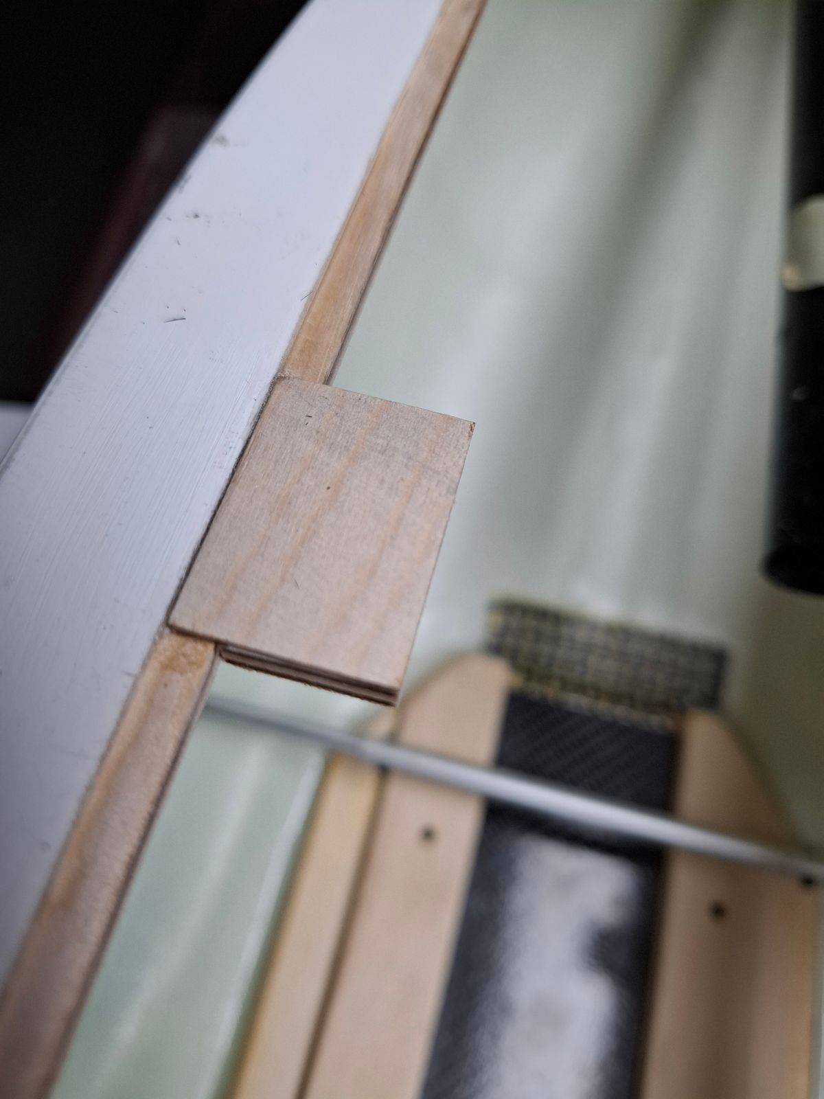
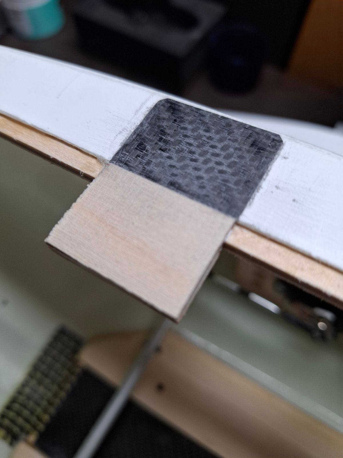
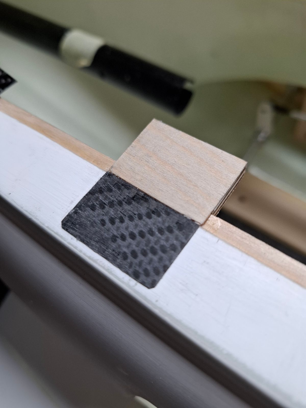
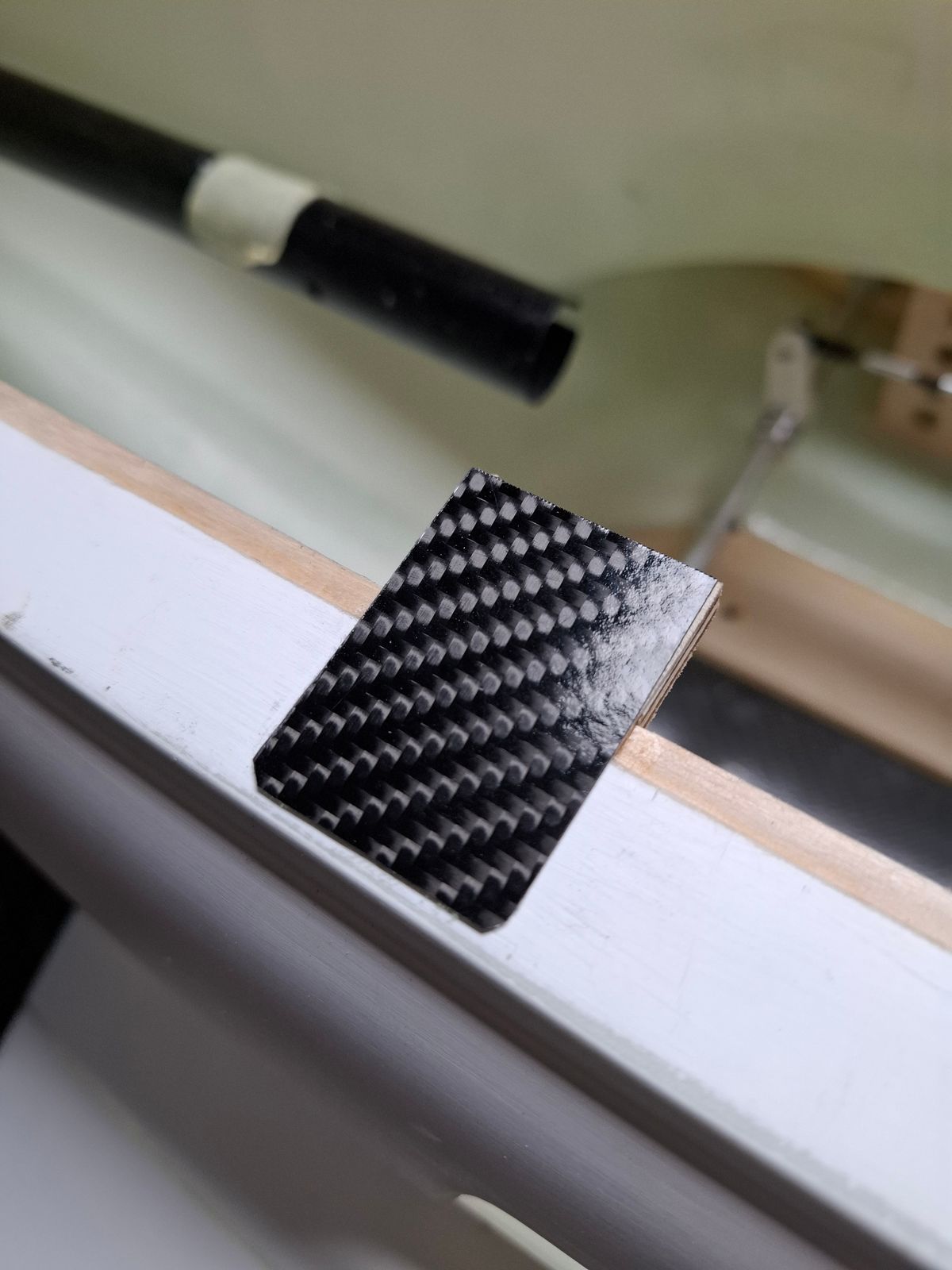
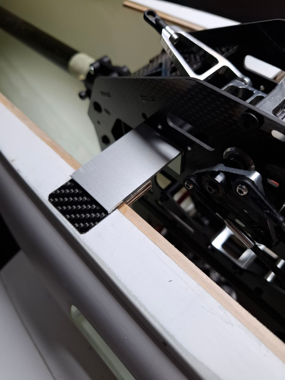
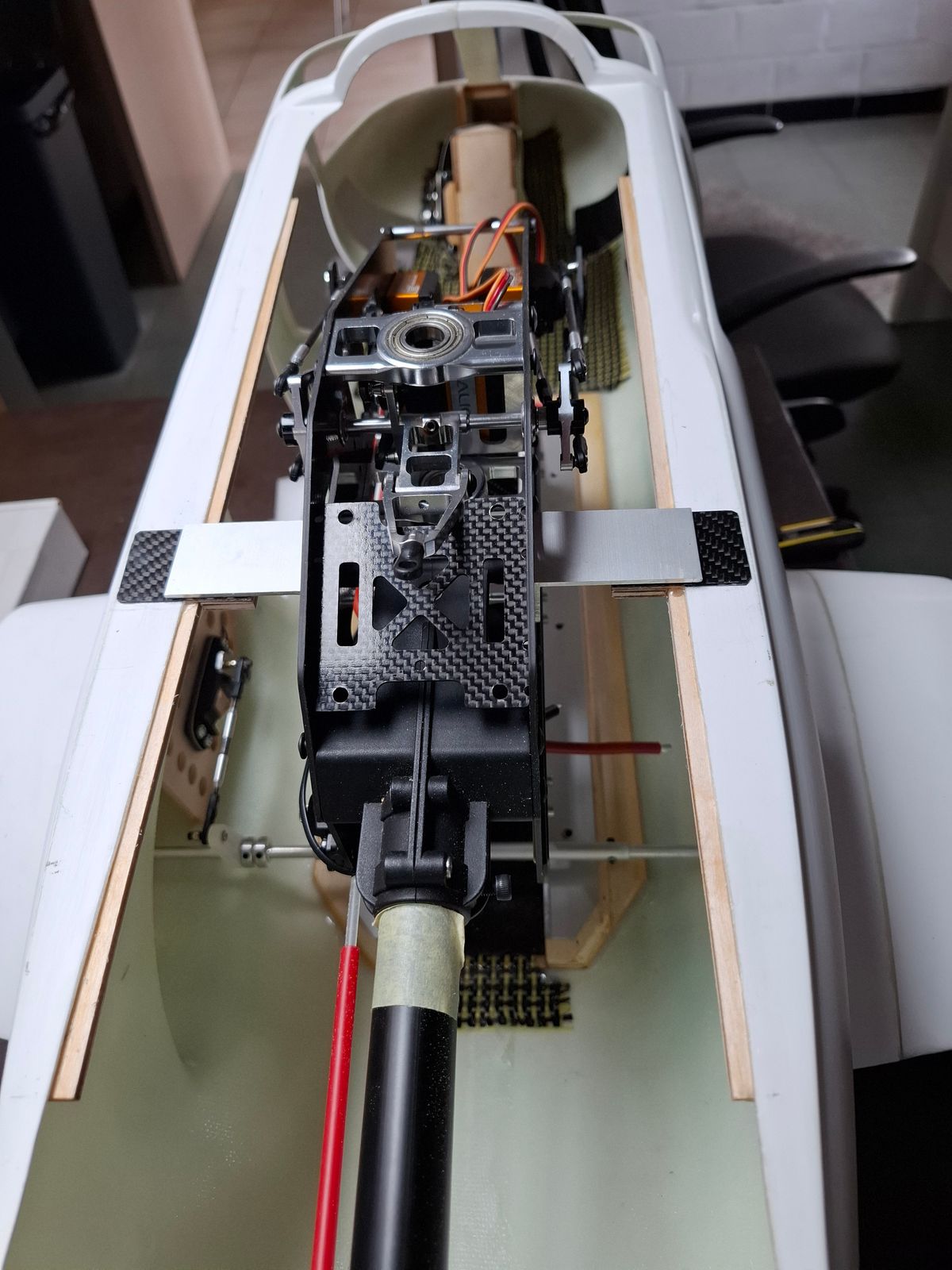
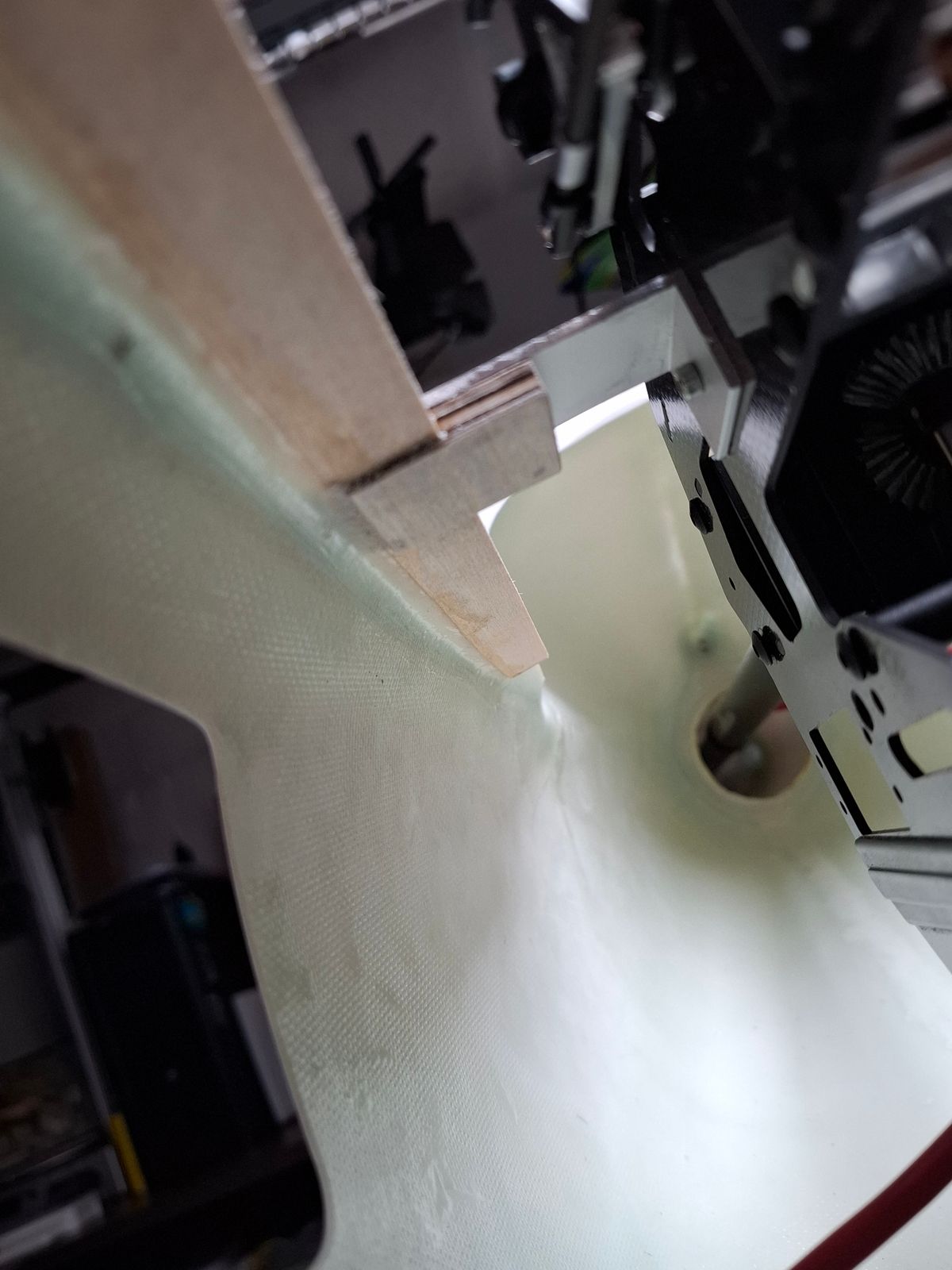
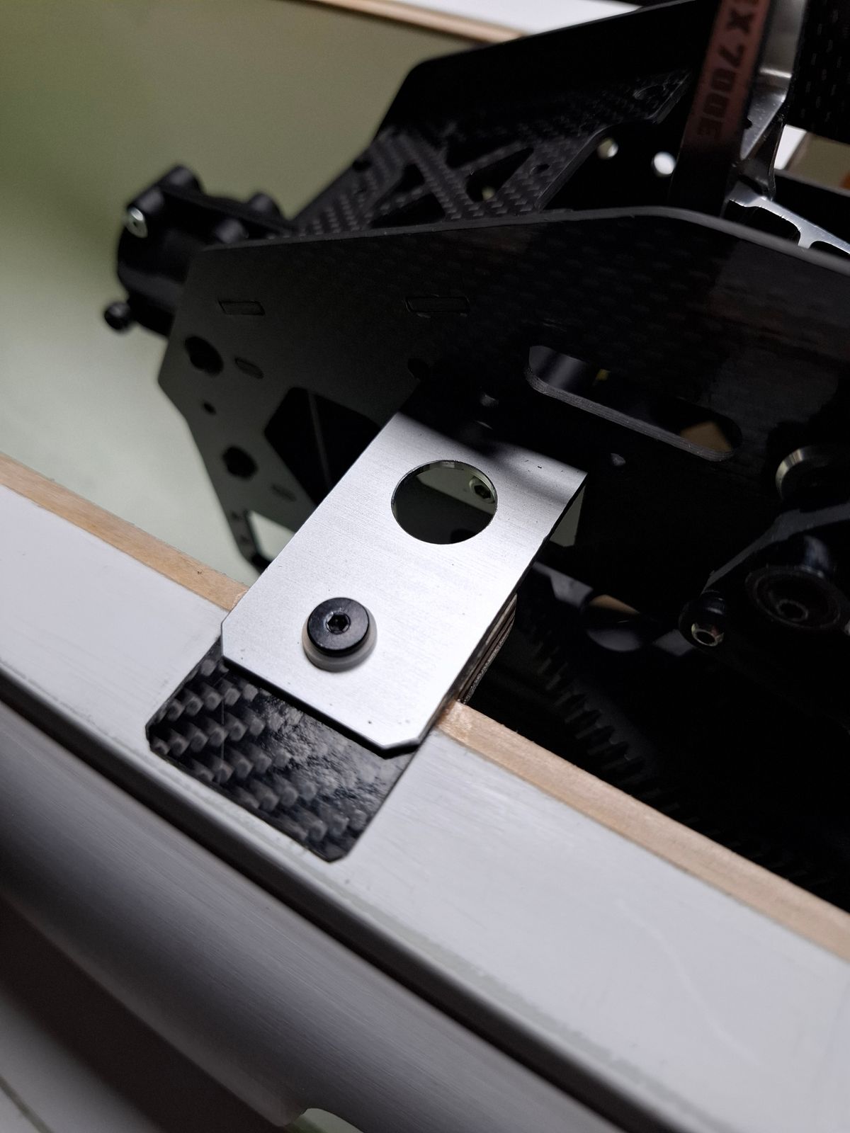
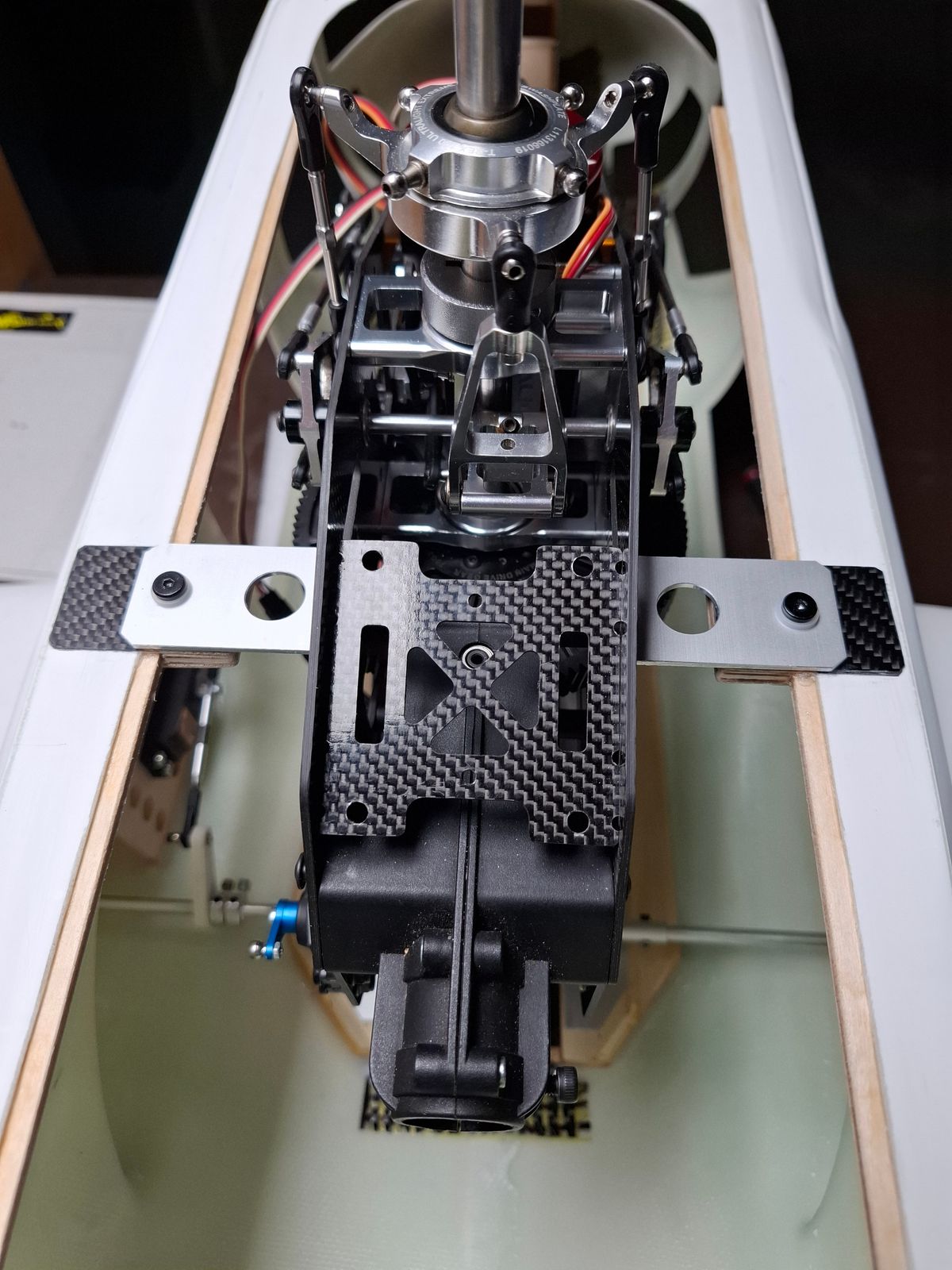
Fuselage reinforcement for mechanic support
Adding some reinforcement strips for mechanics topside connection.
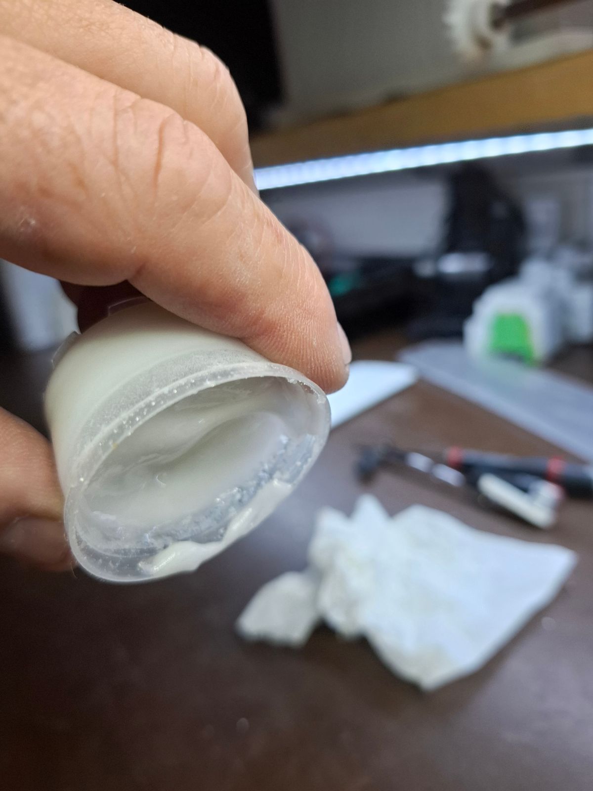
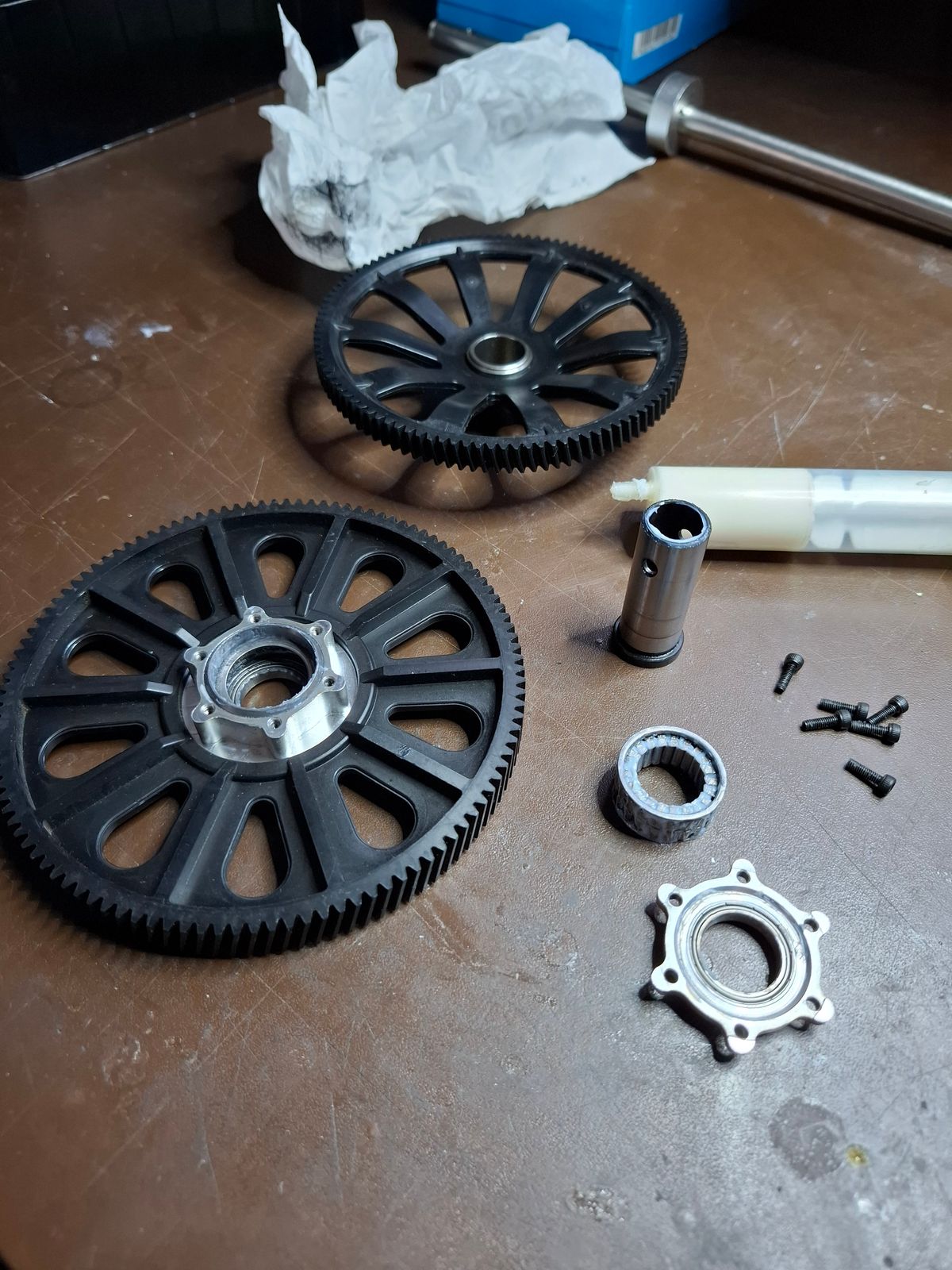
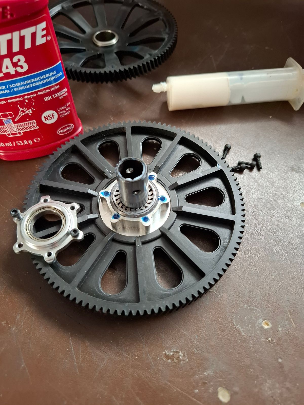
Reverse one way bearing for CCW operation
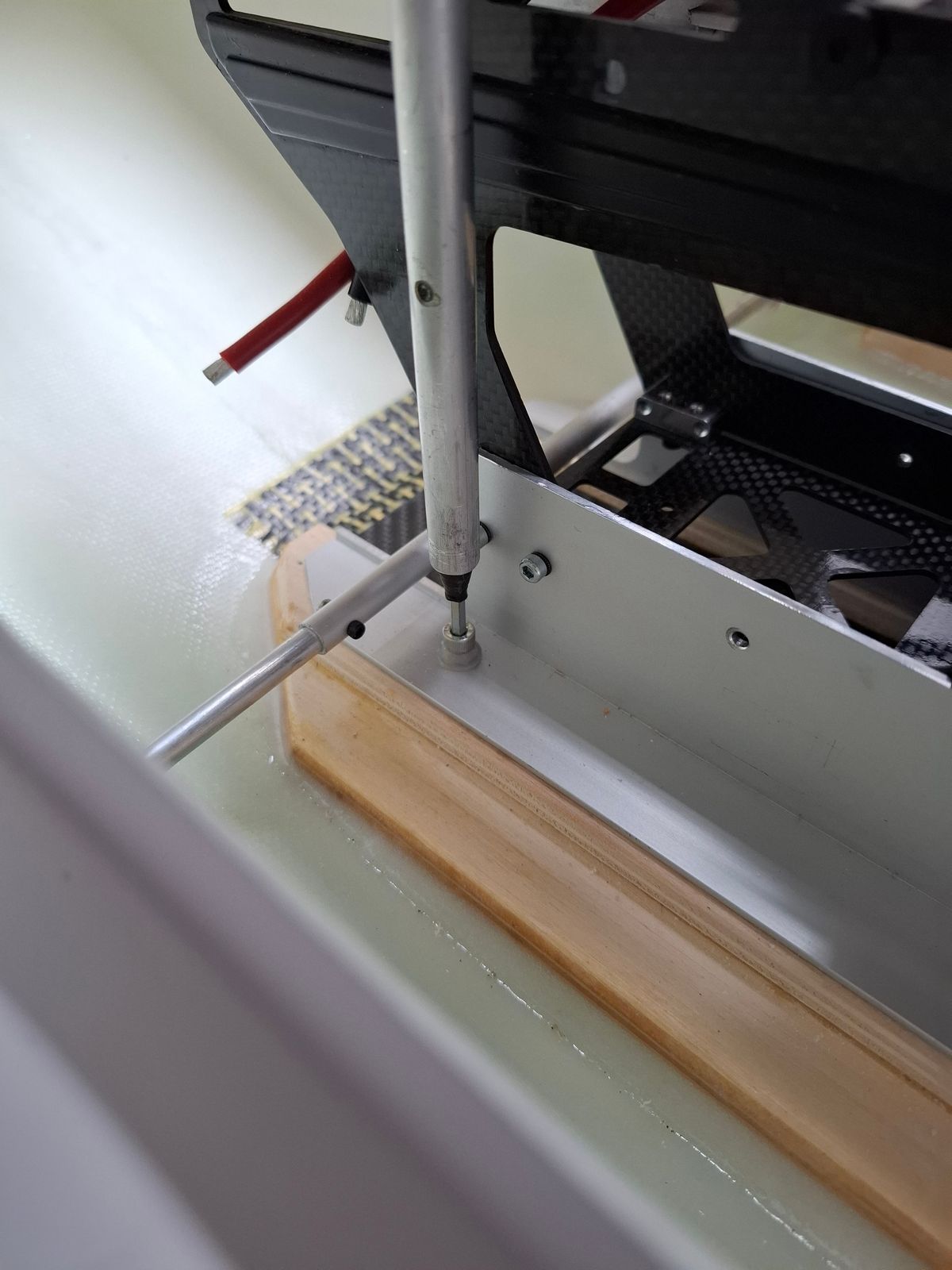
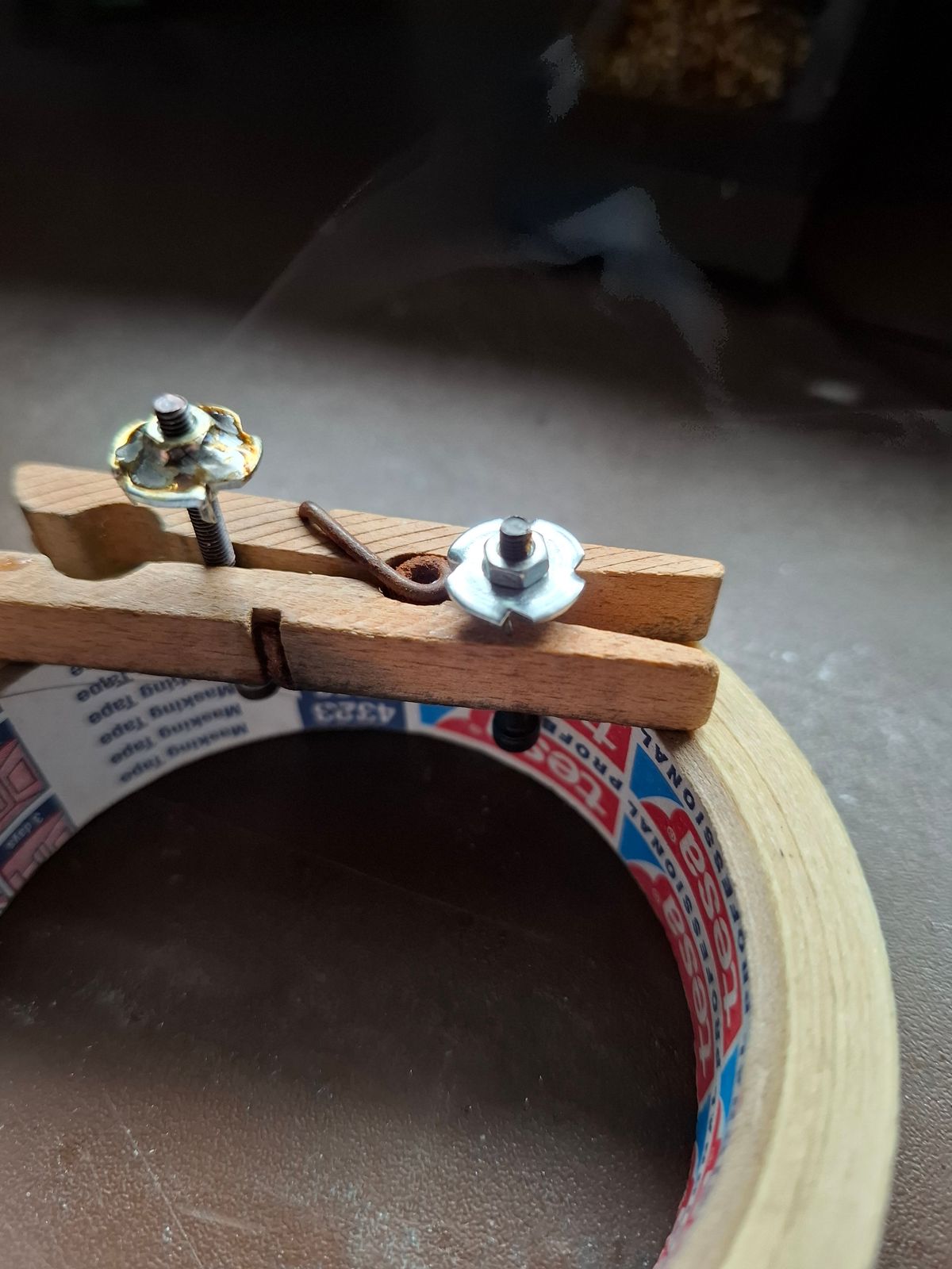
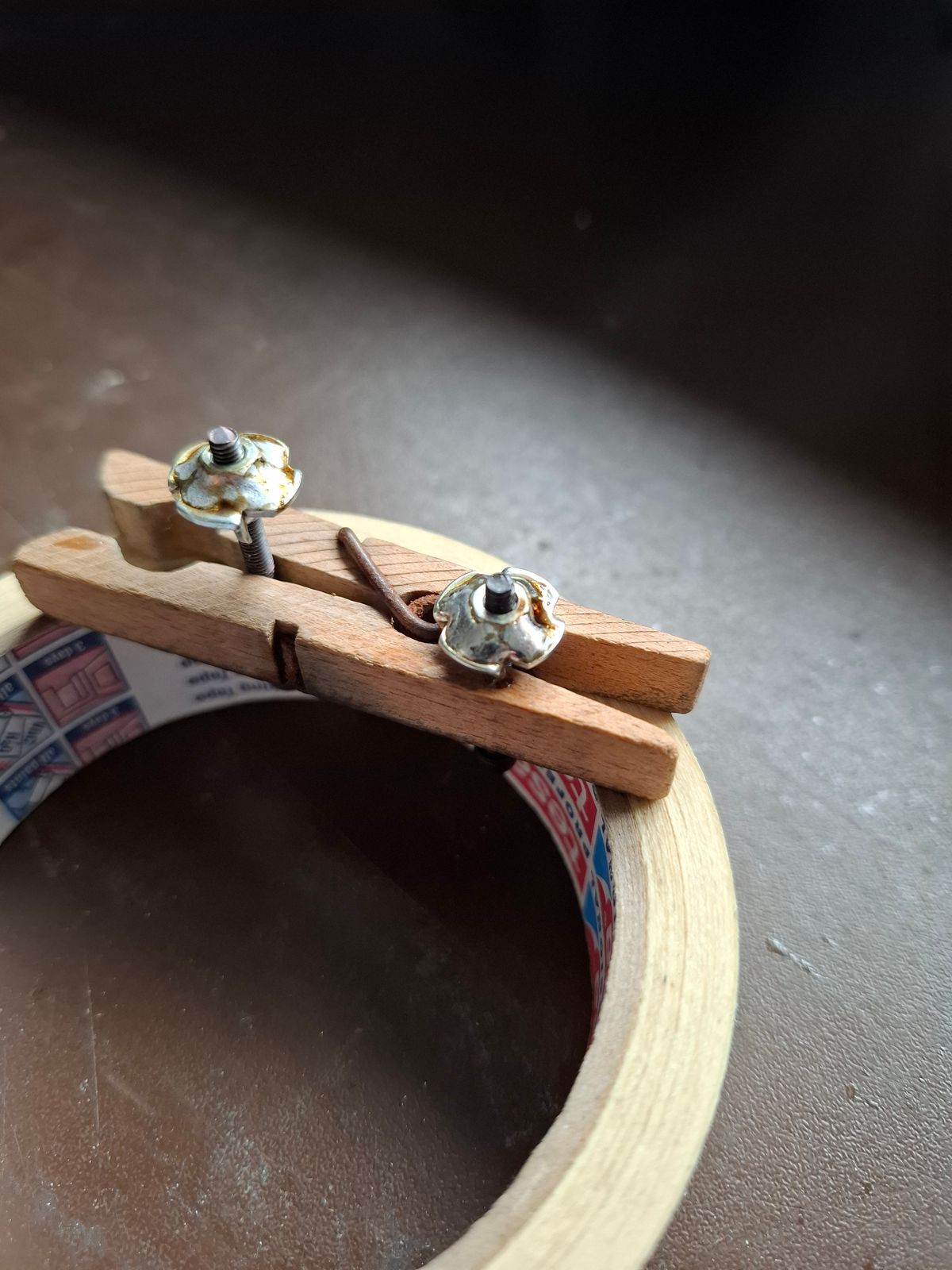
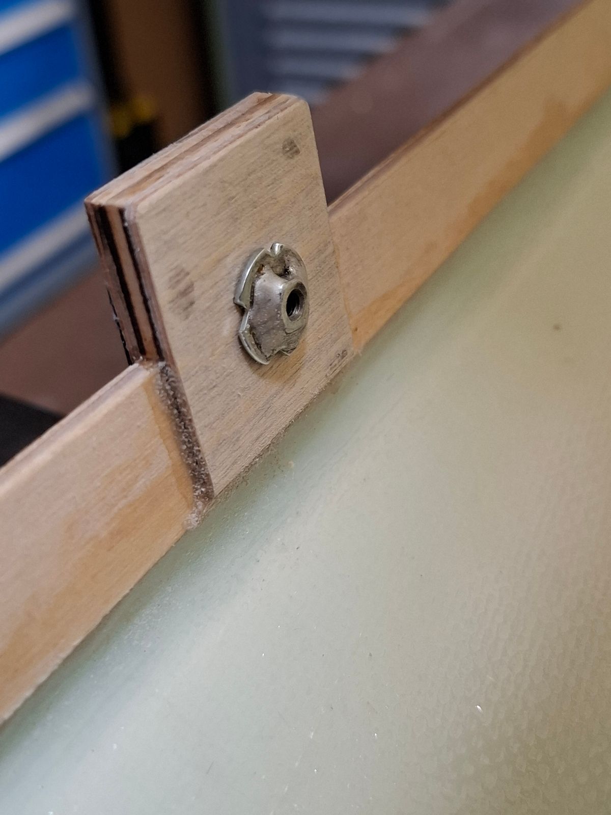
Reinforced insert nuts
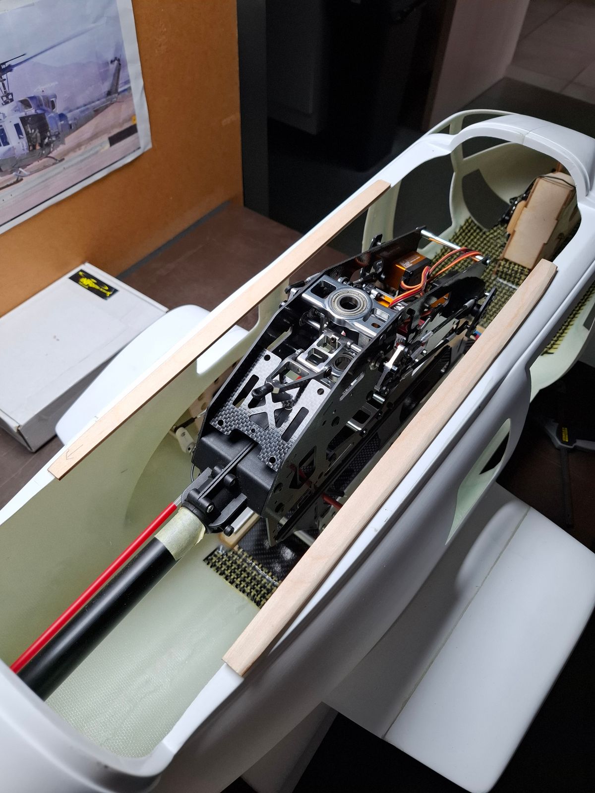
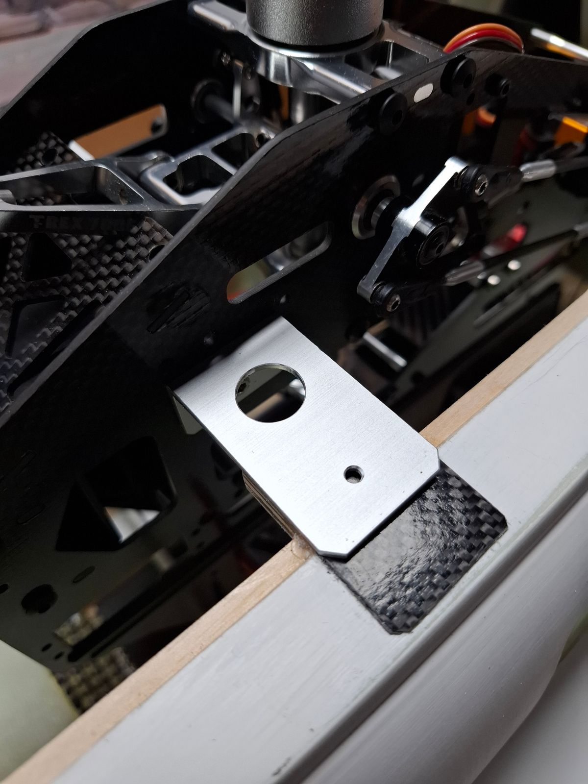
Easy acces thru alu supports for rear bolt of mechanic attachment
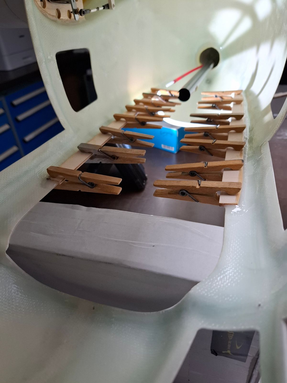
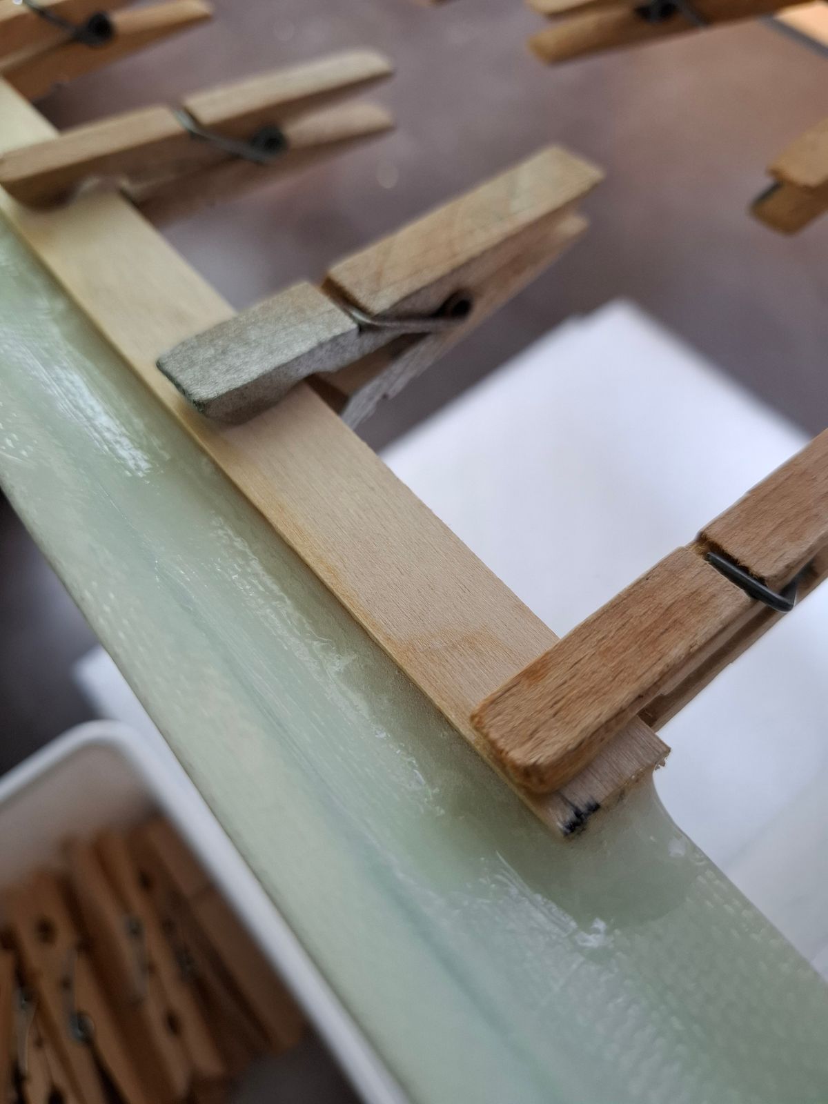
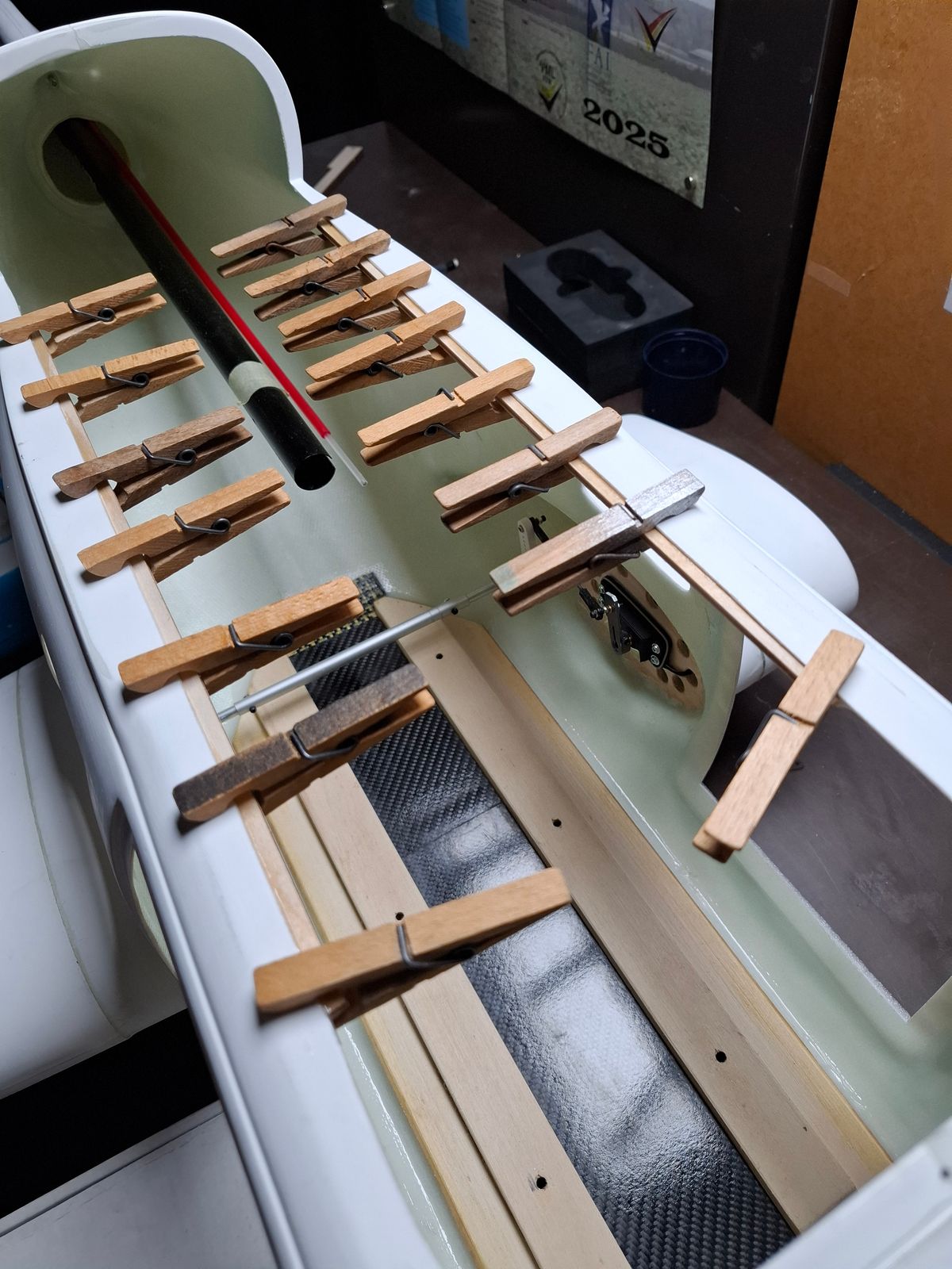
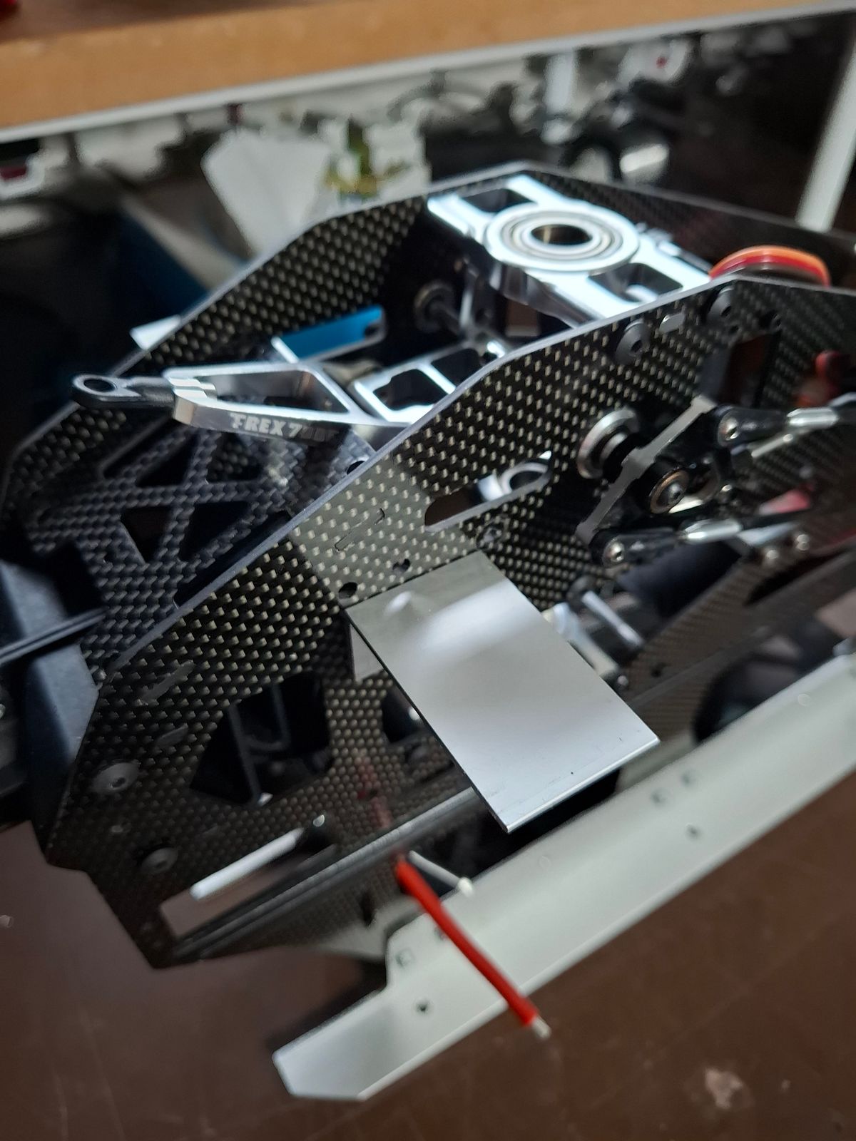
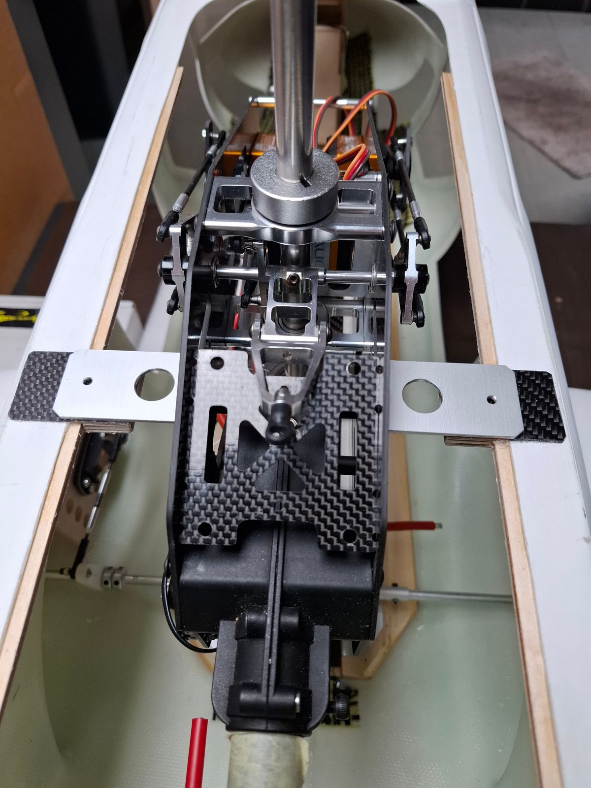
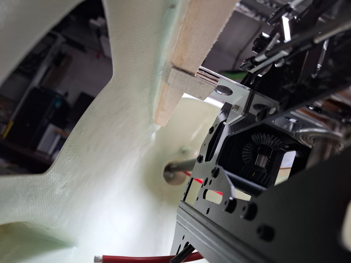
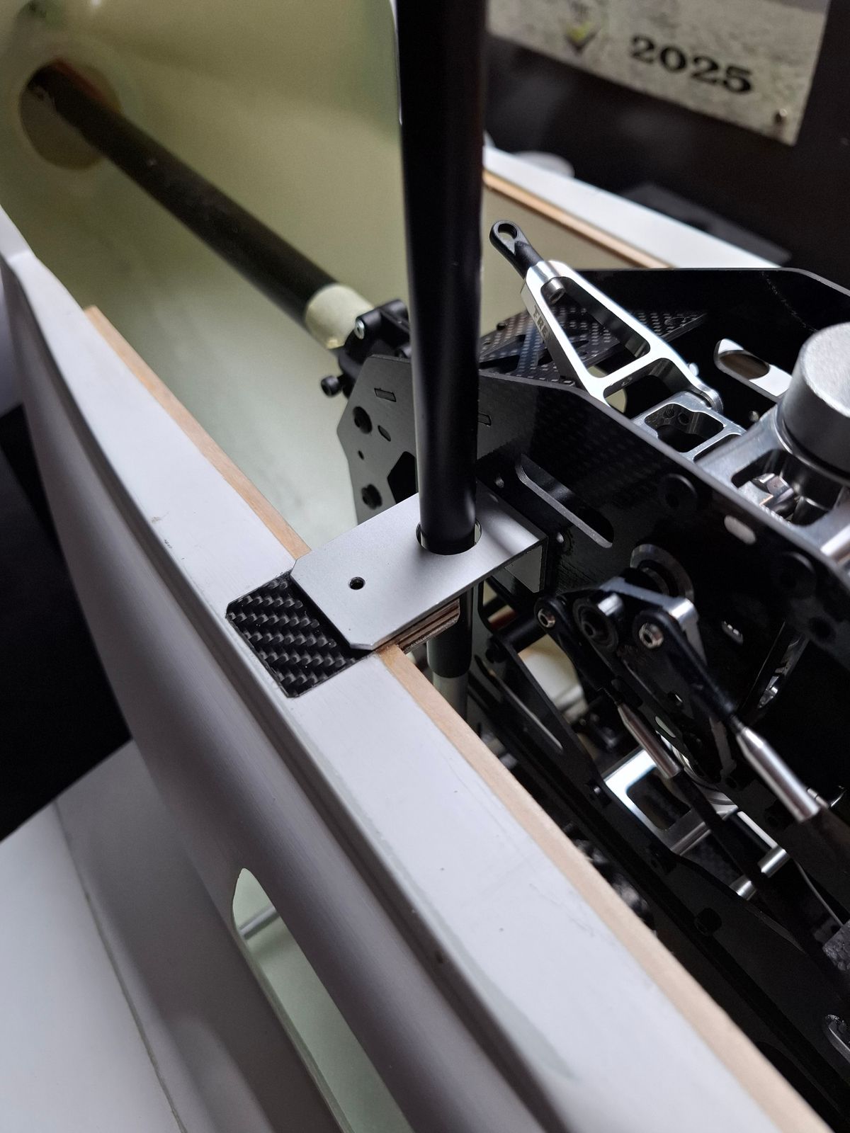
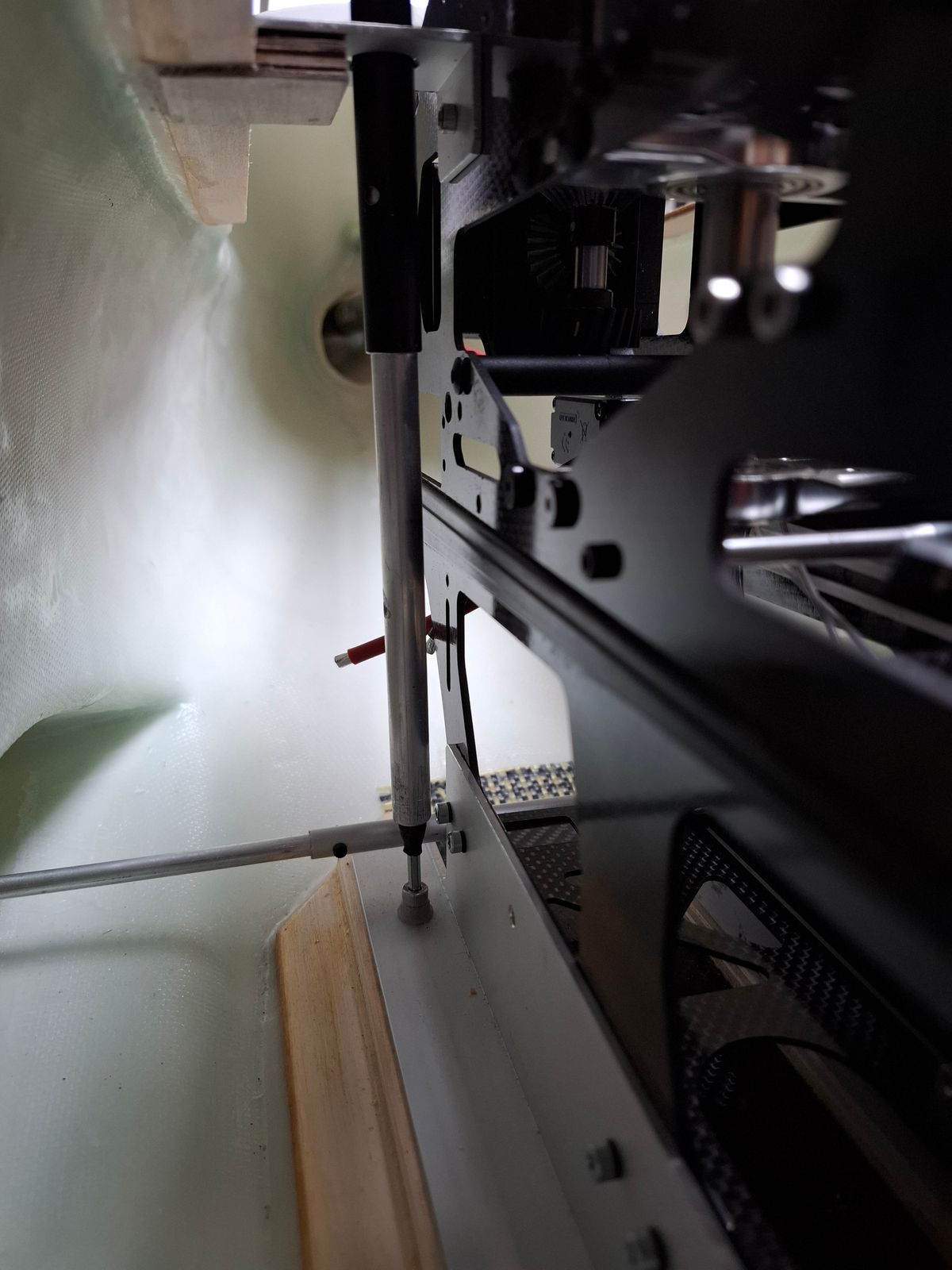
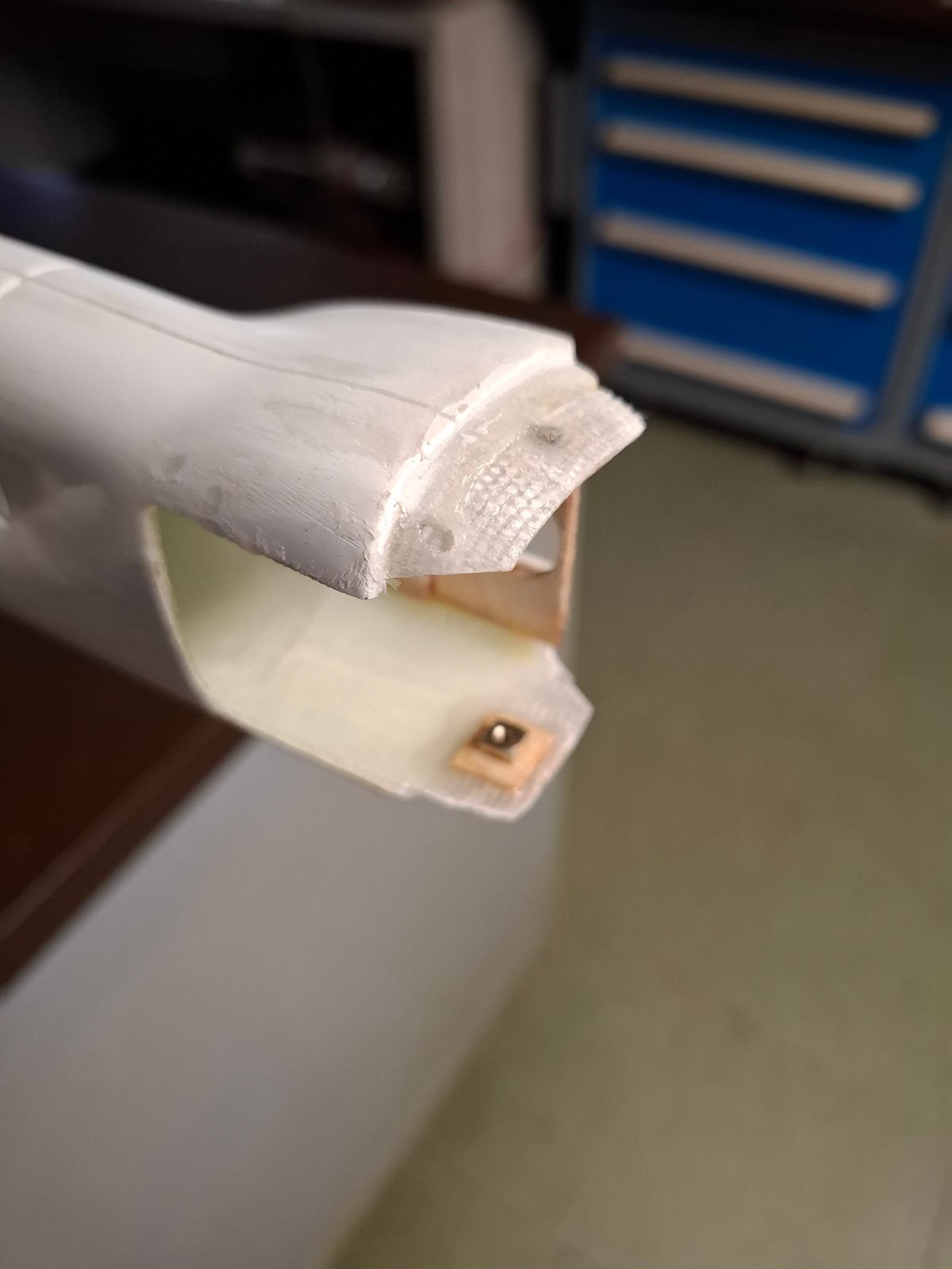
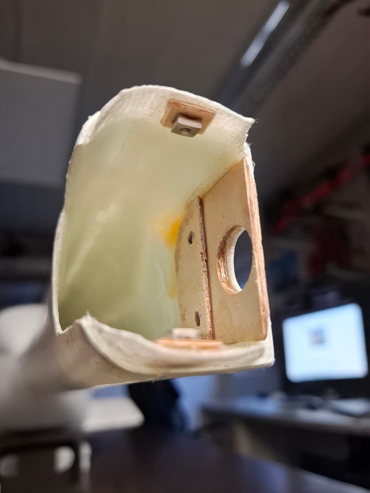
Fuselage modification and navi lights prep
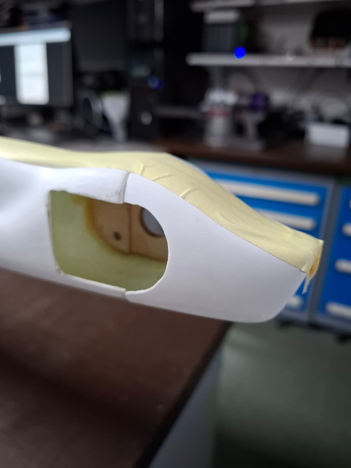
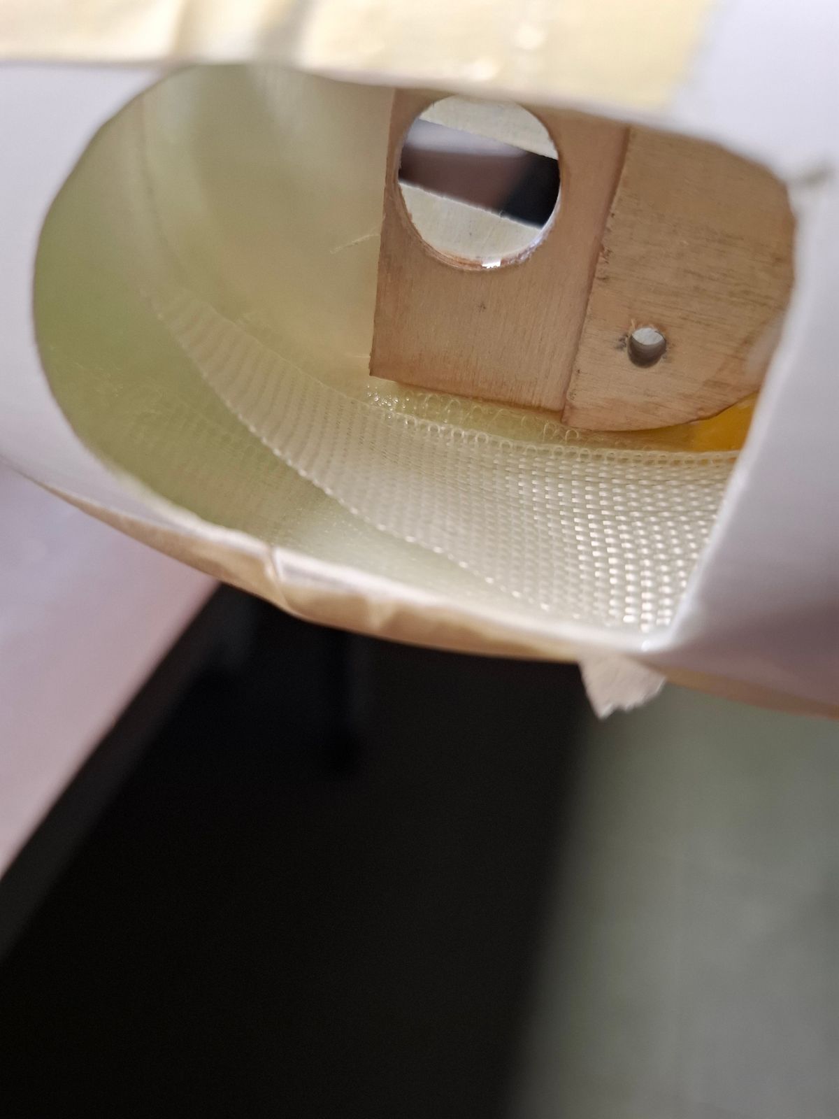
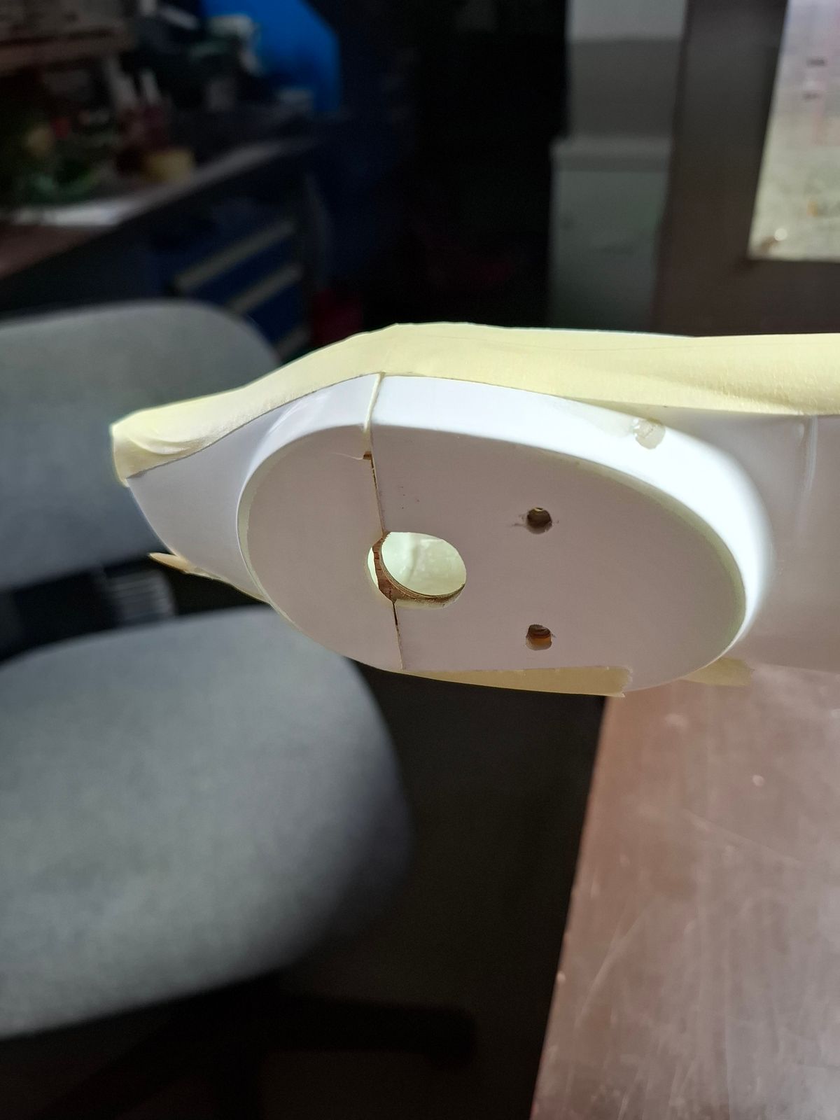
Modification tailcone due to no good fitting of the original
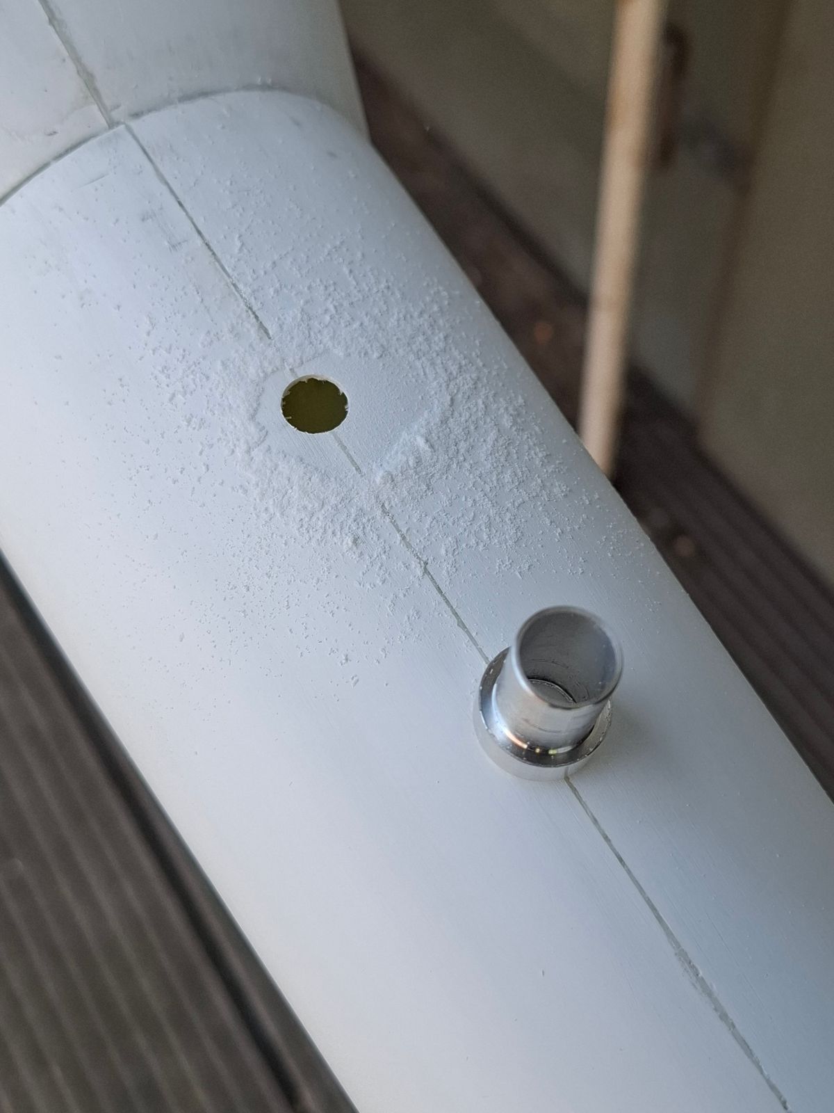
Inserts for tailcone attachment
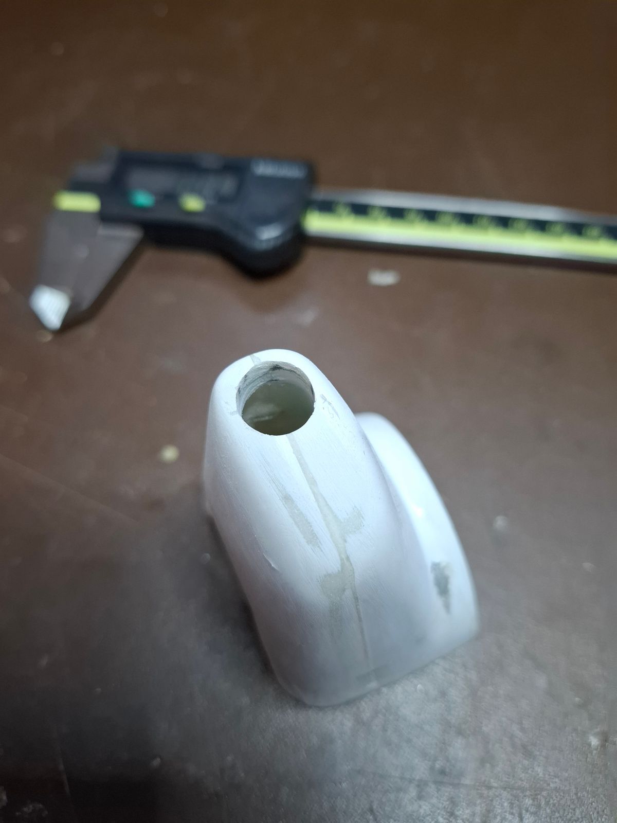
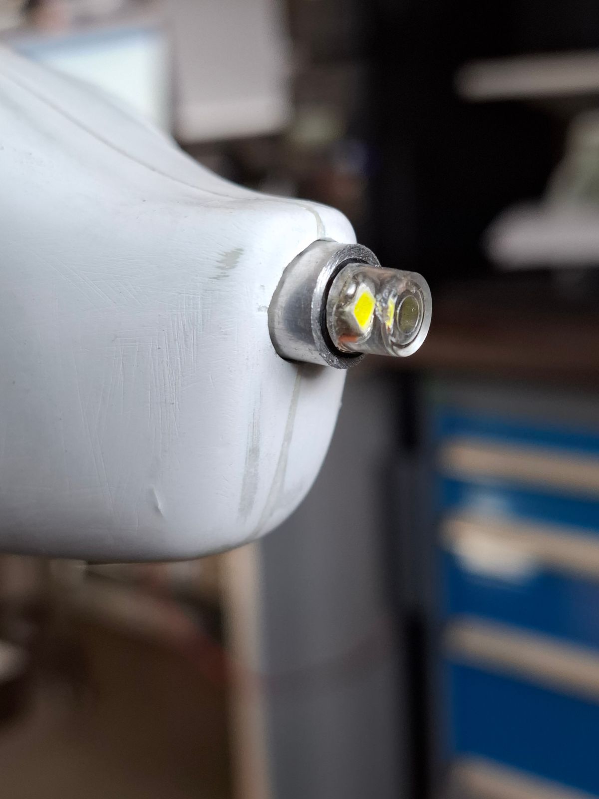
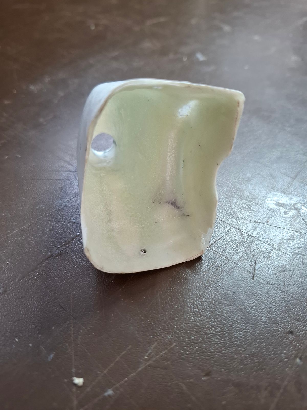
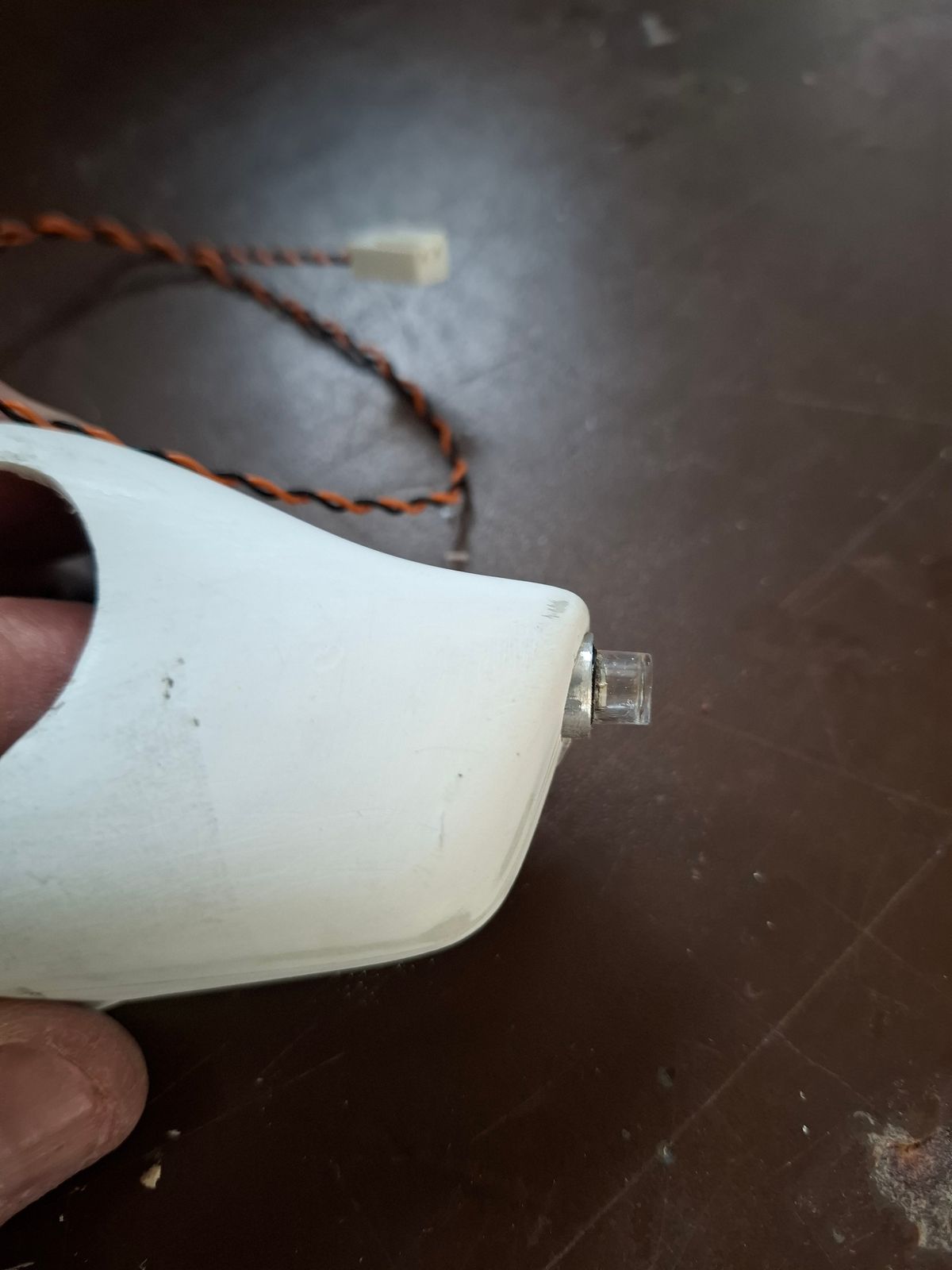
Preparation navigation light tail cone
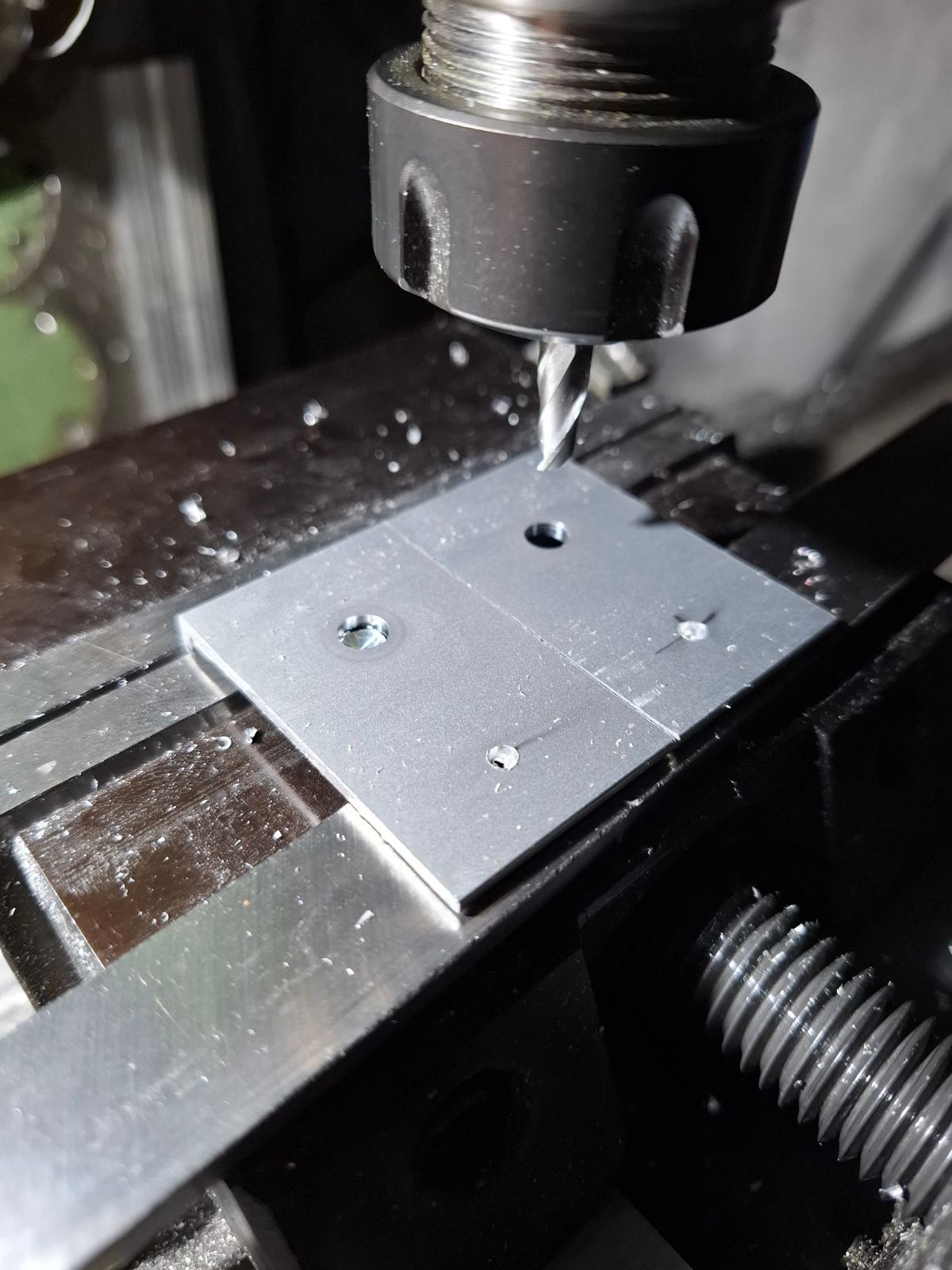
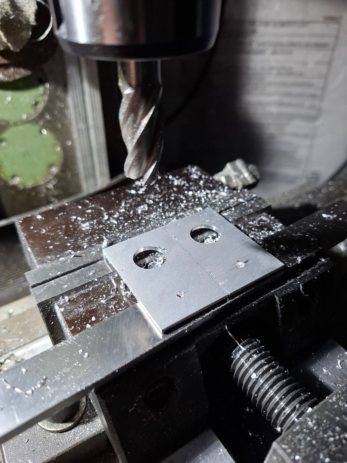
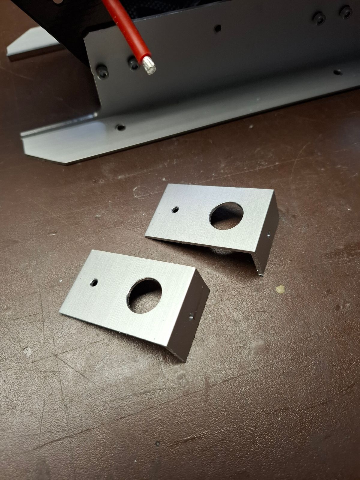
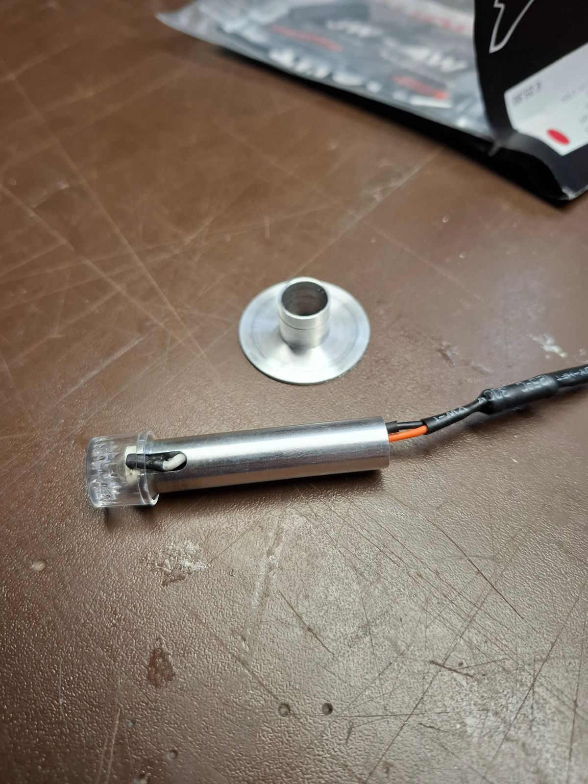
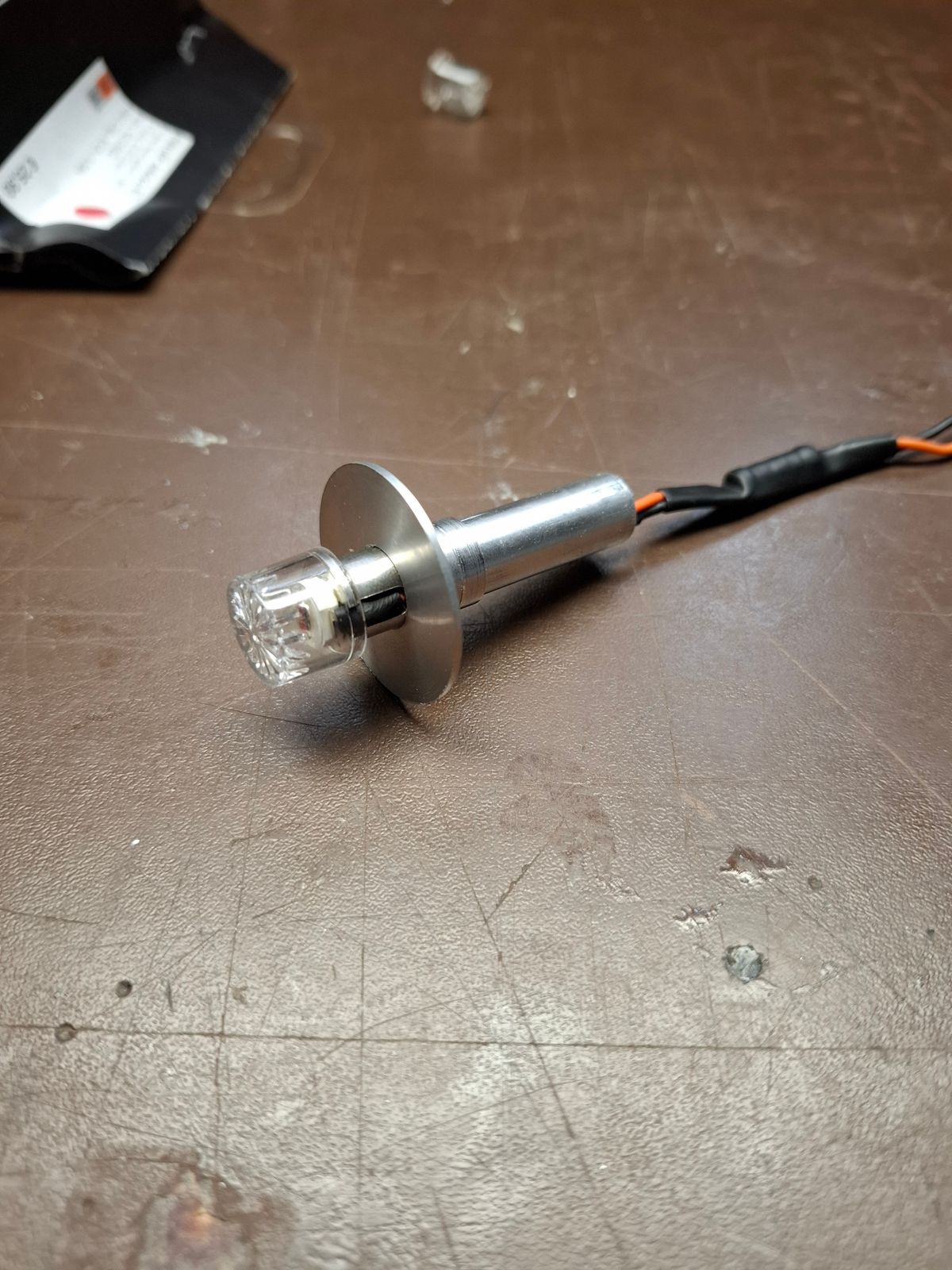
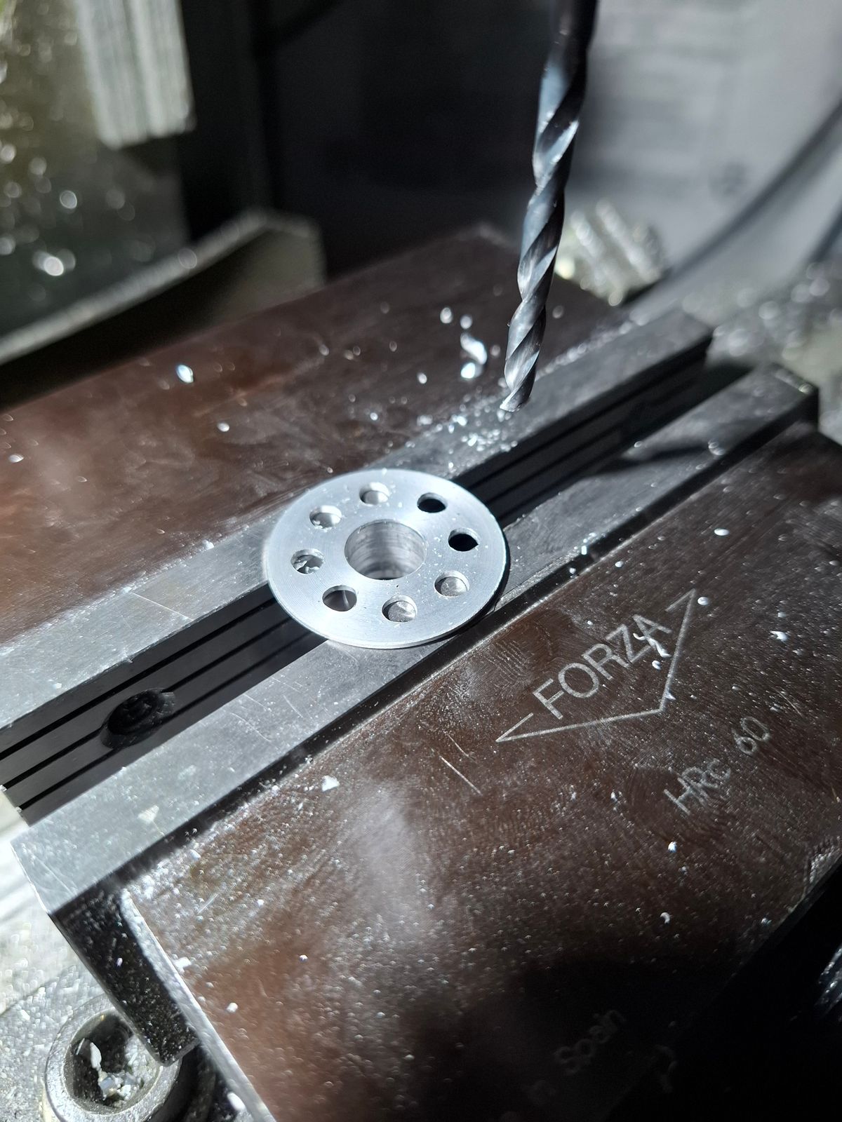
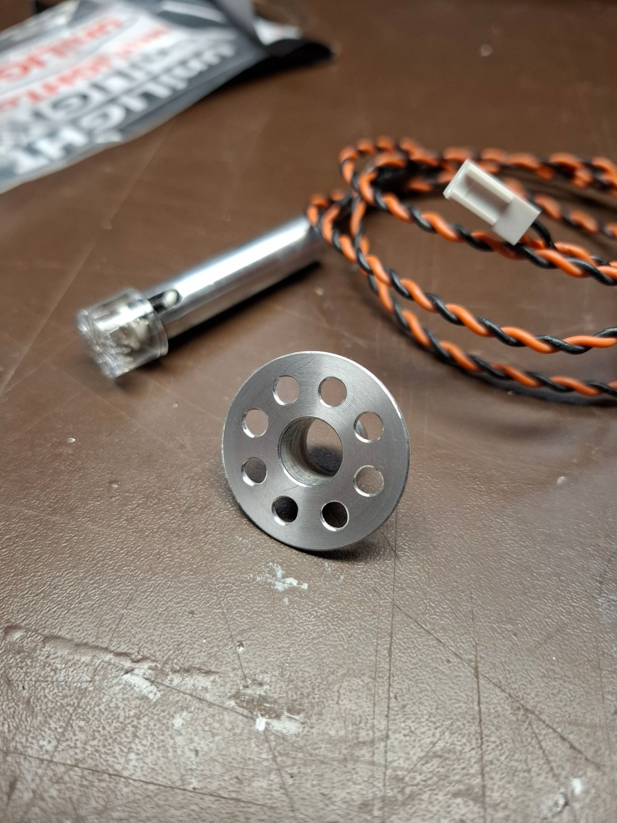
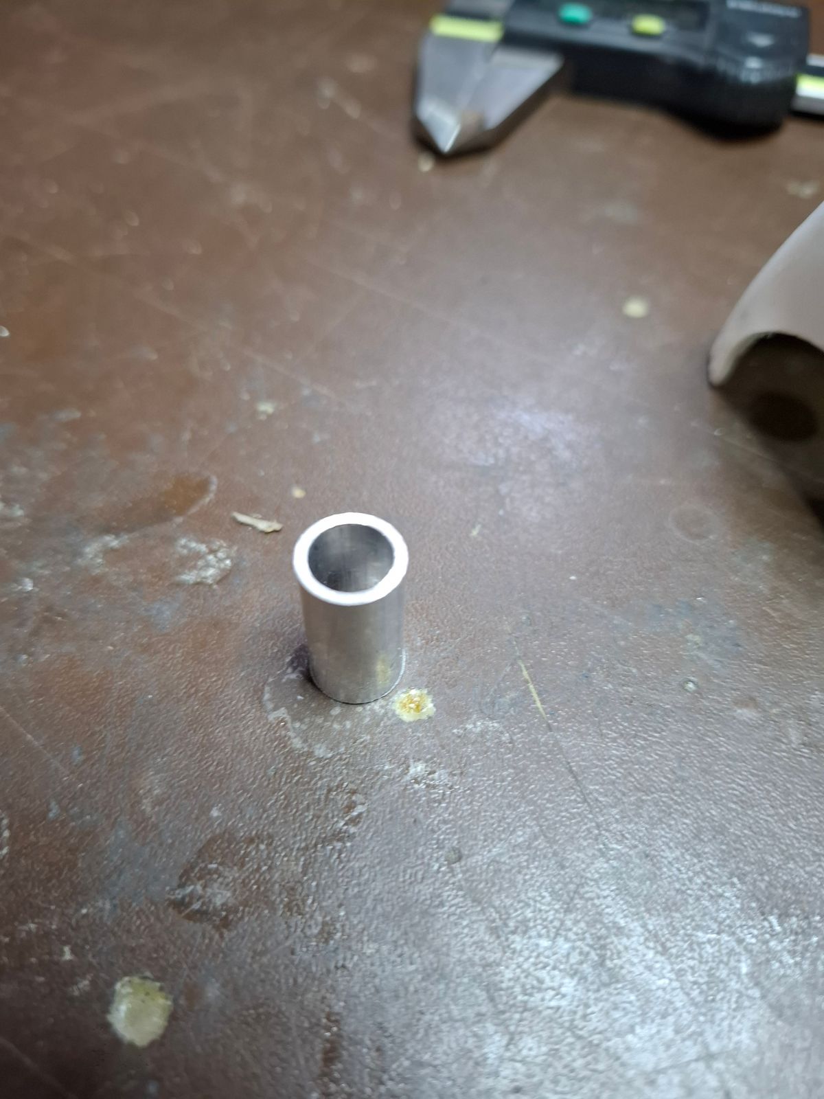
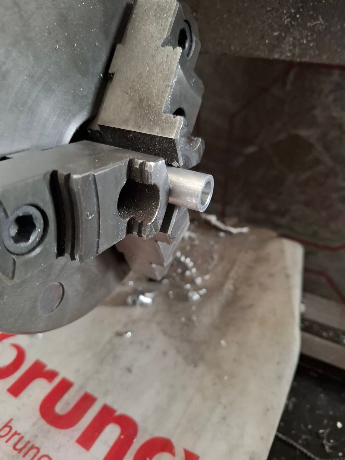
Machining supports for navi light tailboom and doghouse
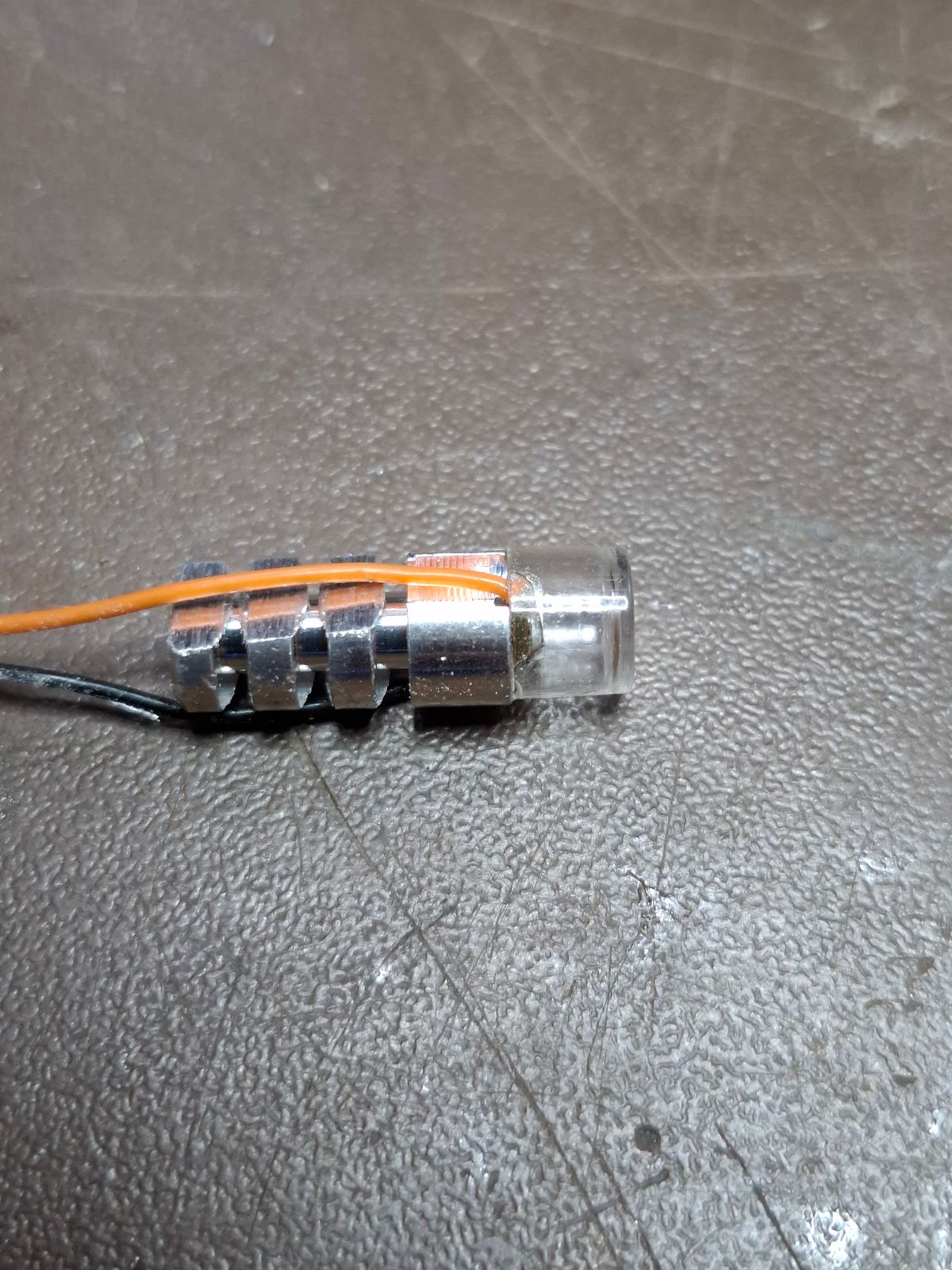
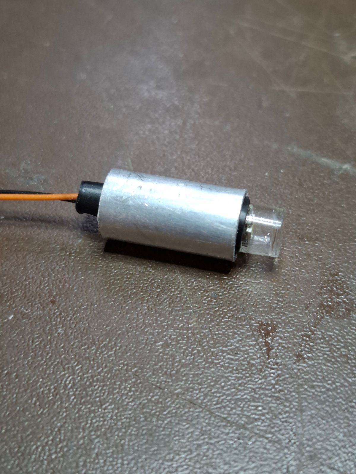
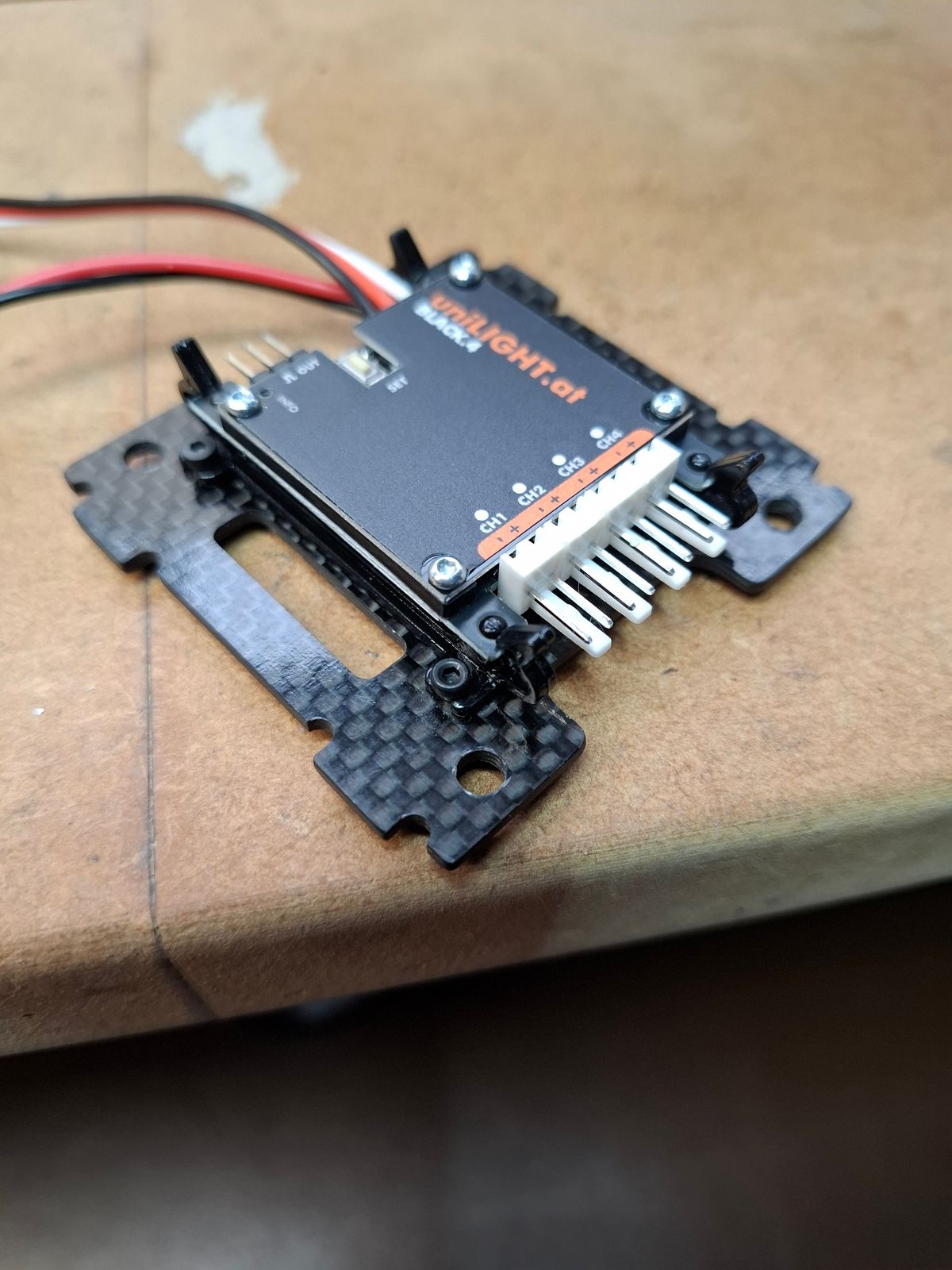
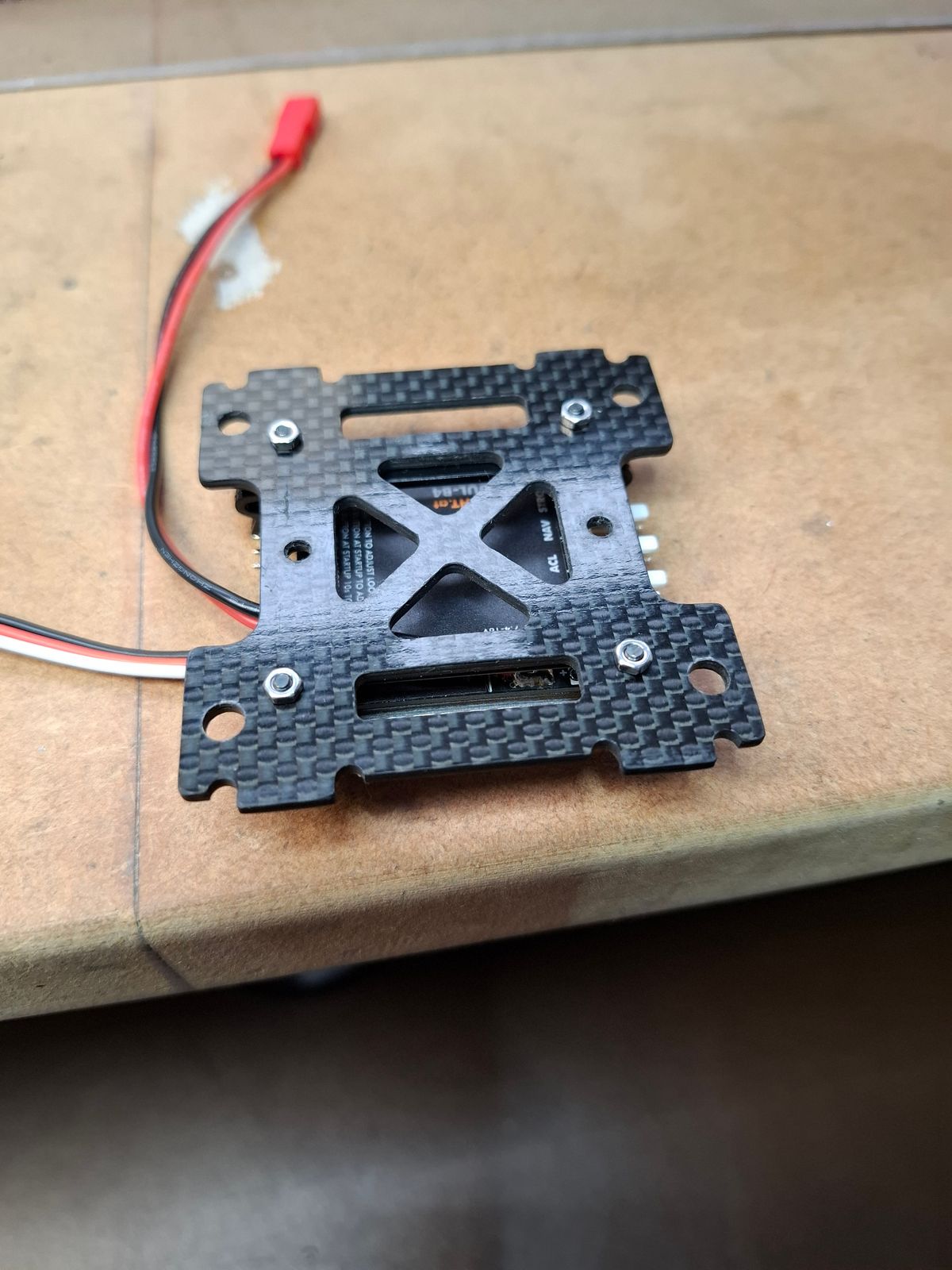
Unilight lights. (Unilight.at)
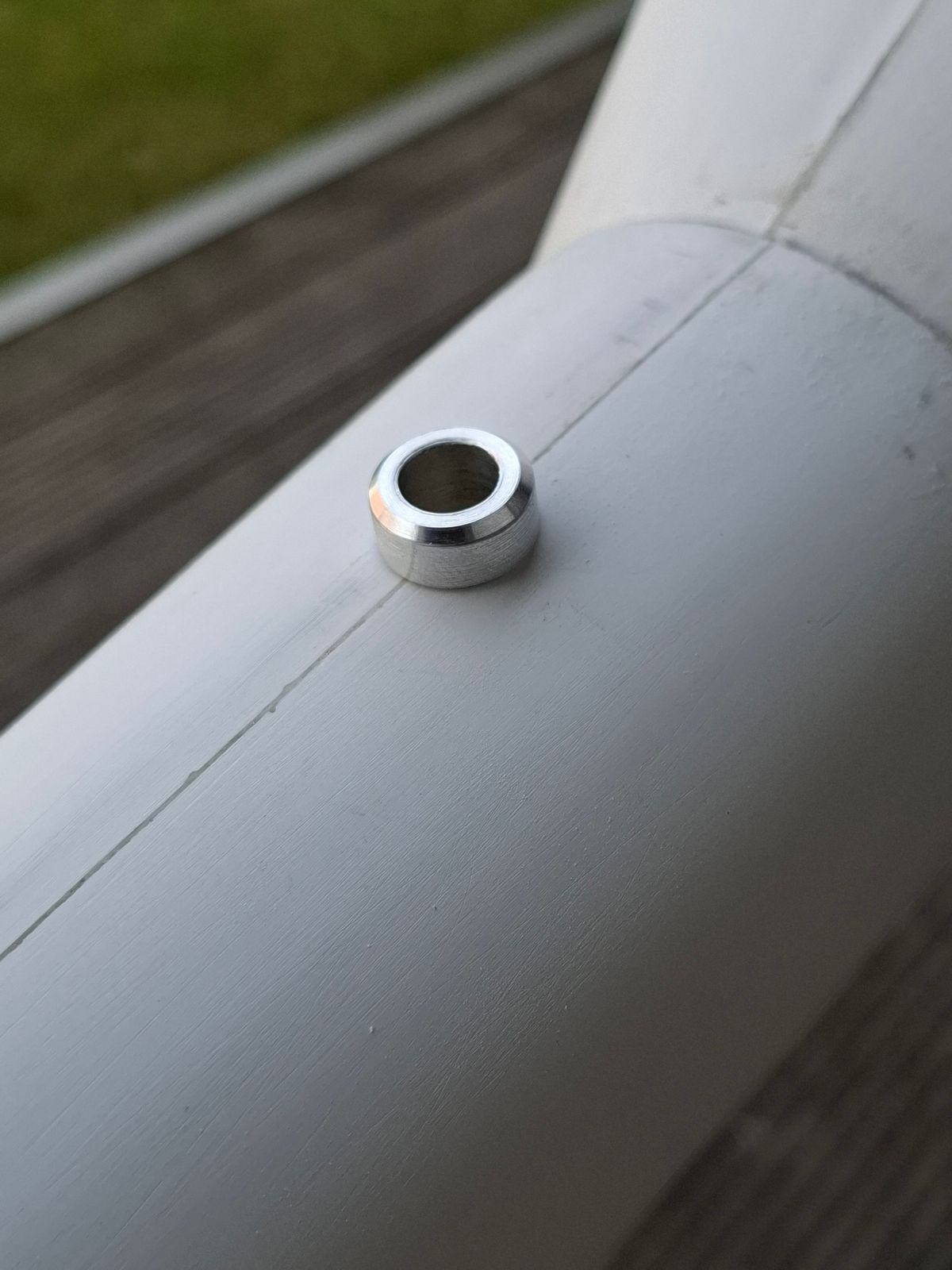
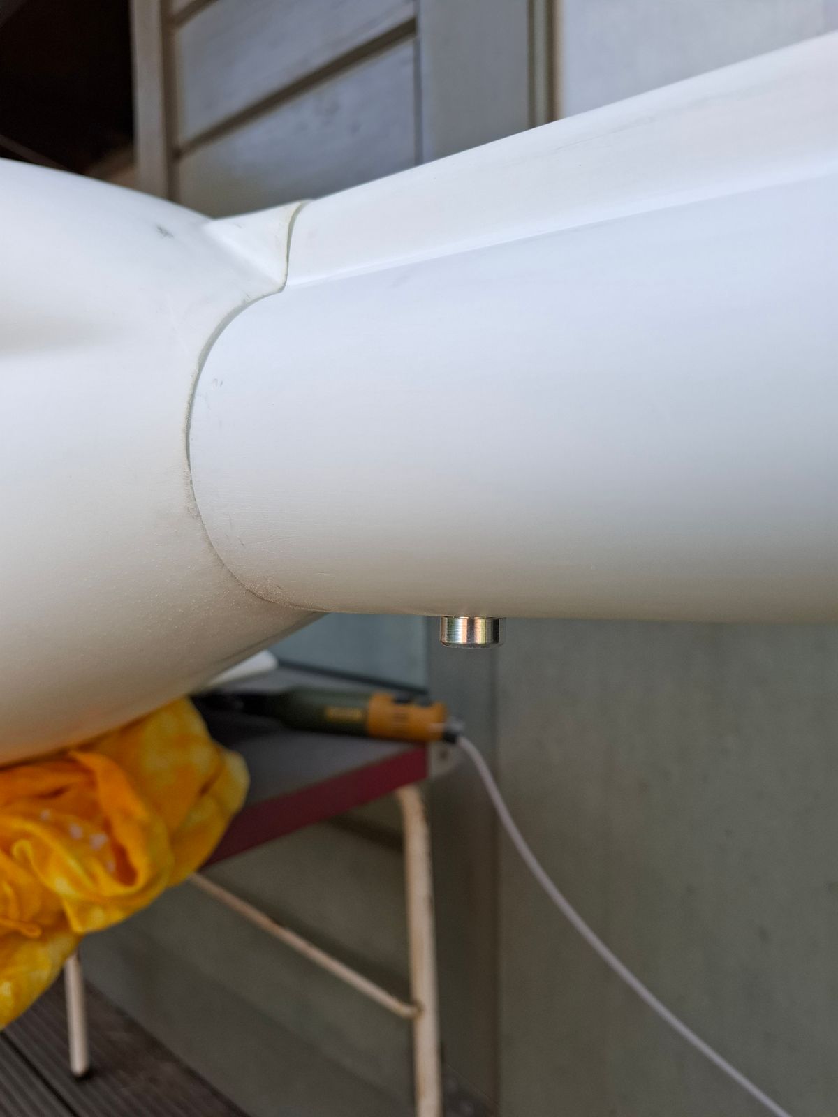
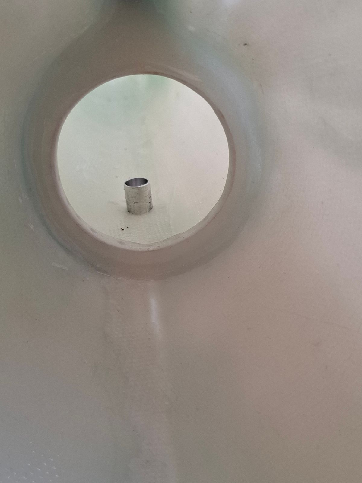
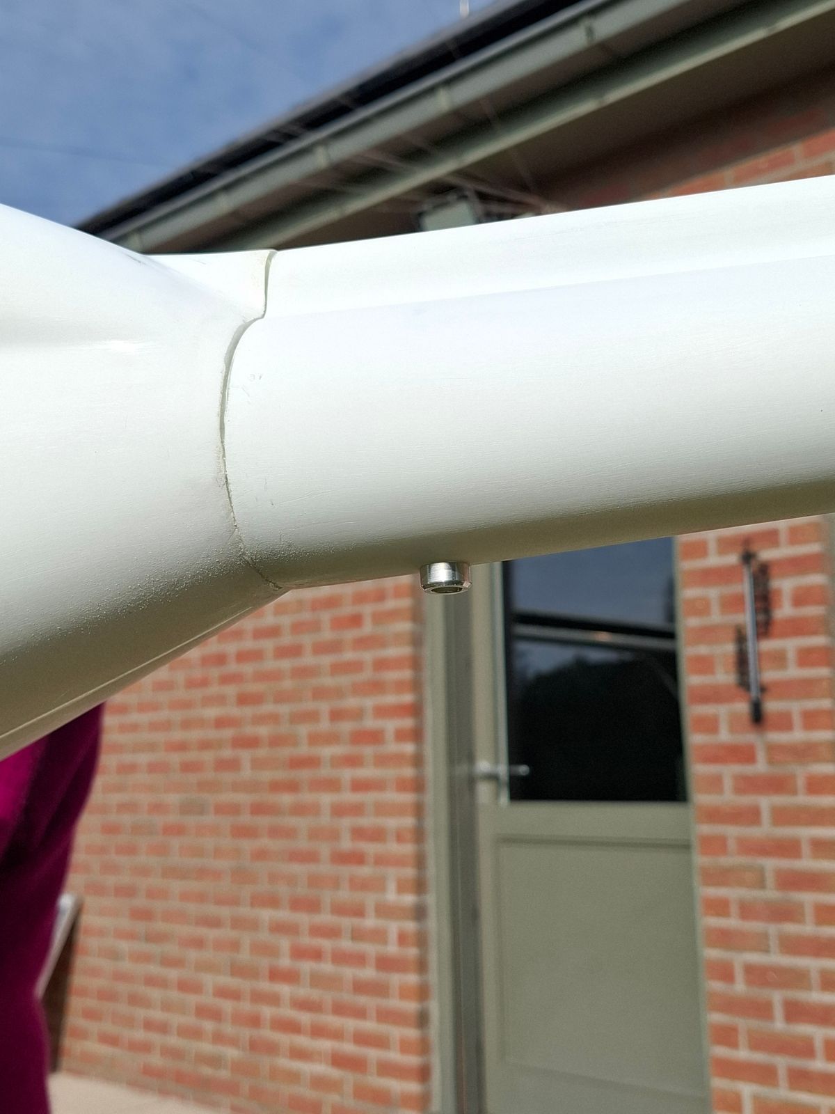
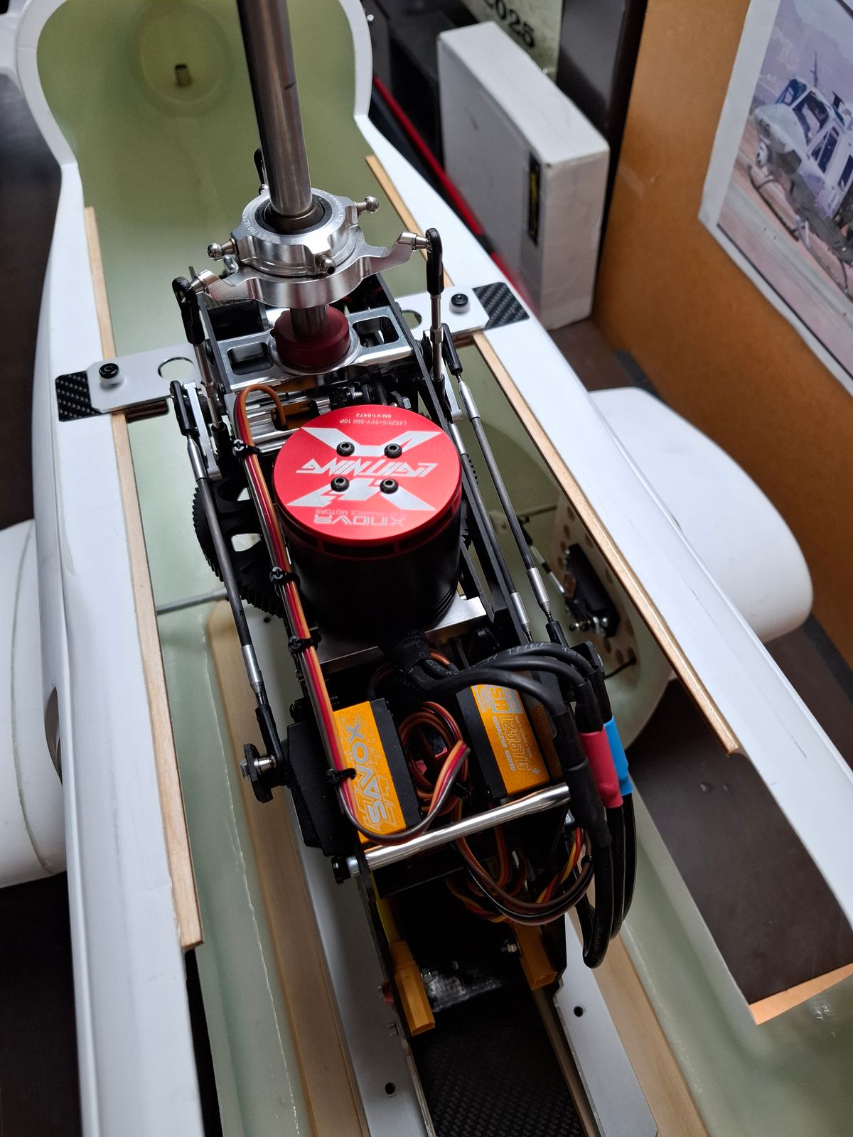
Mechanics and electronics setup and wiring
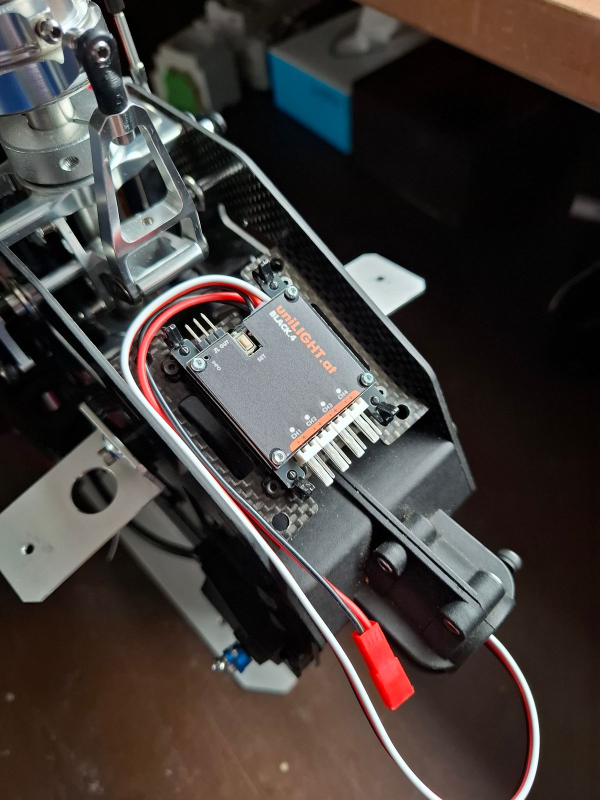
Unilight navigation light controller setup
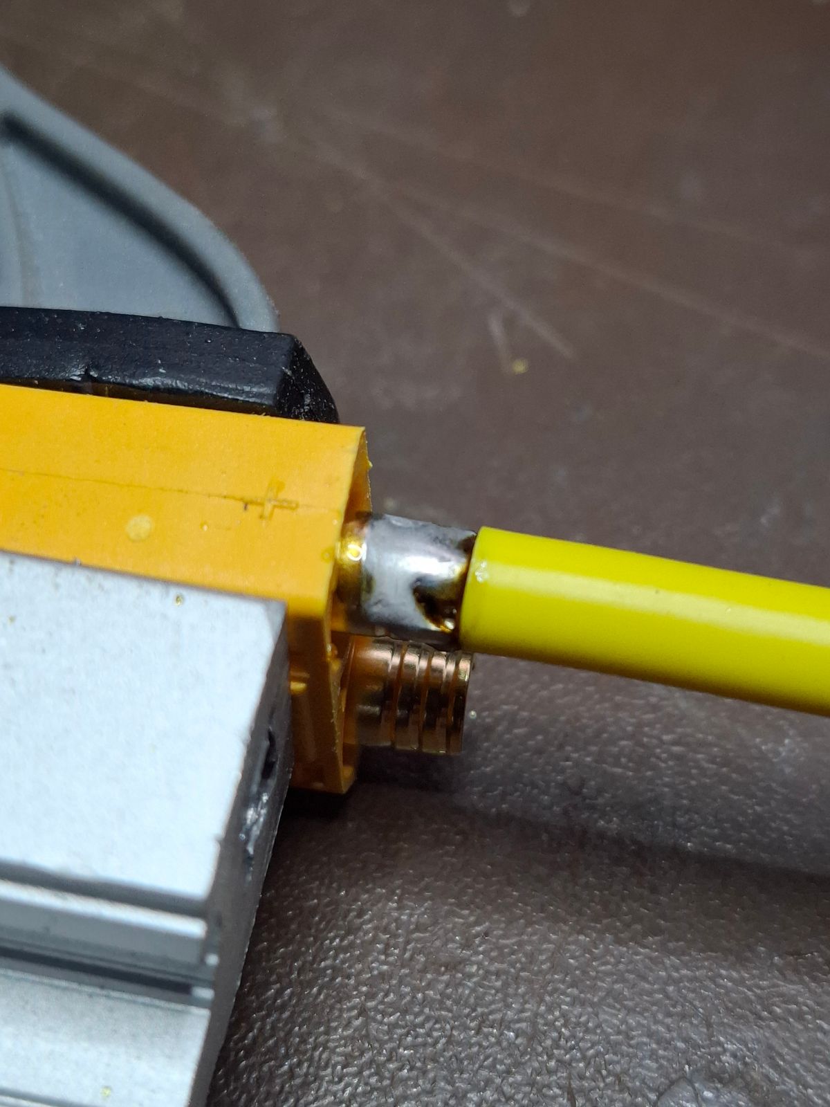
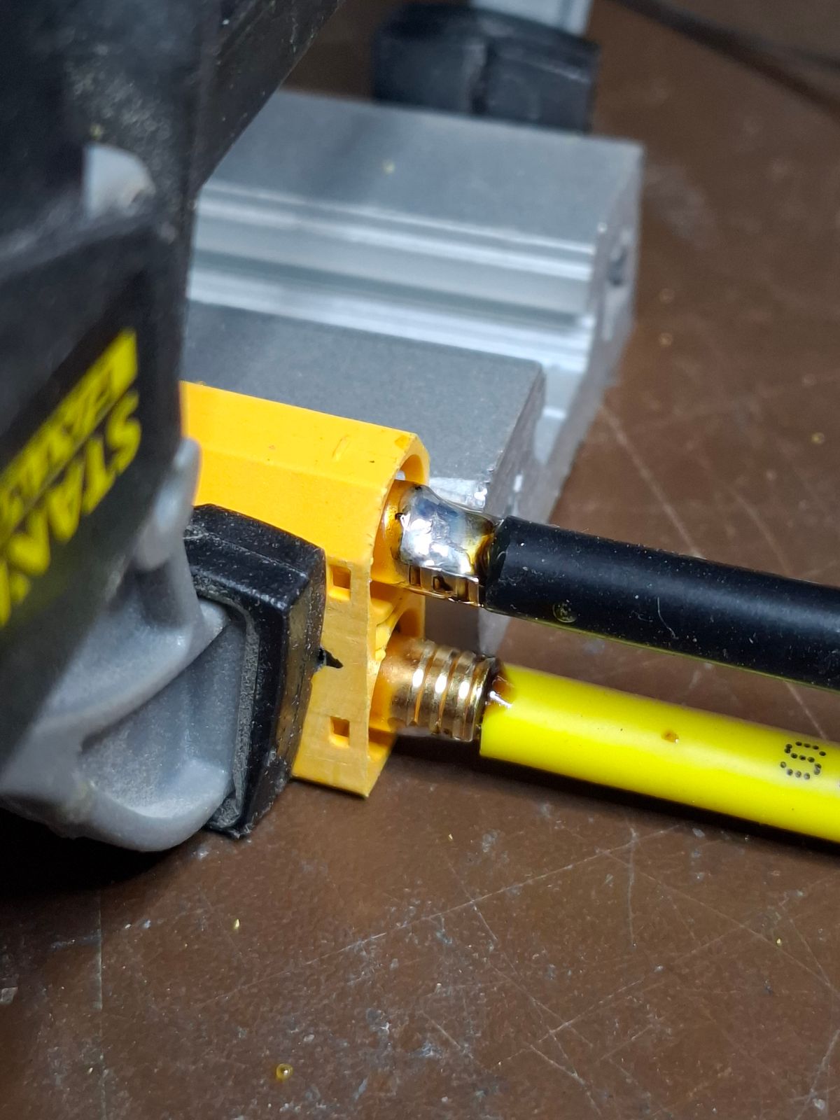
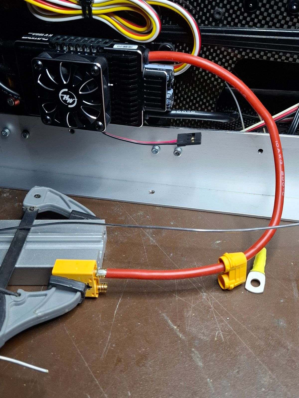
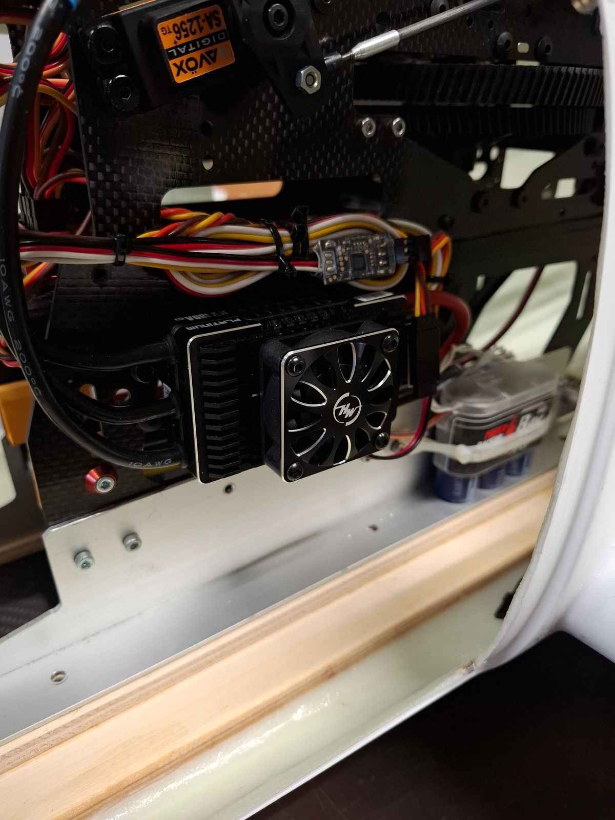
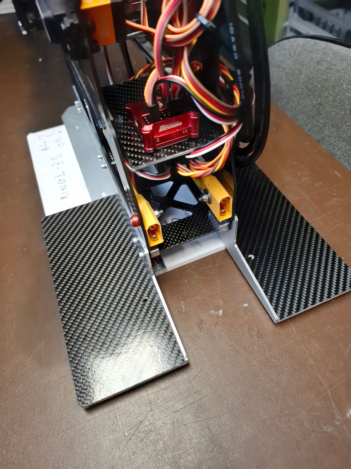
ESC power wiring and connector routing setup
Milling pockets for the door magnets
Additional rotation support for retract drive shaft
Mounting of the door hinges
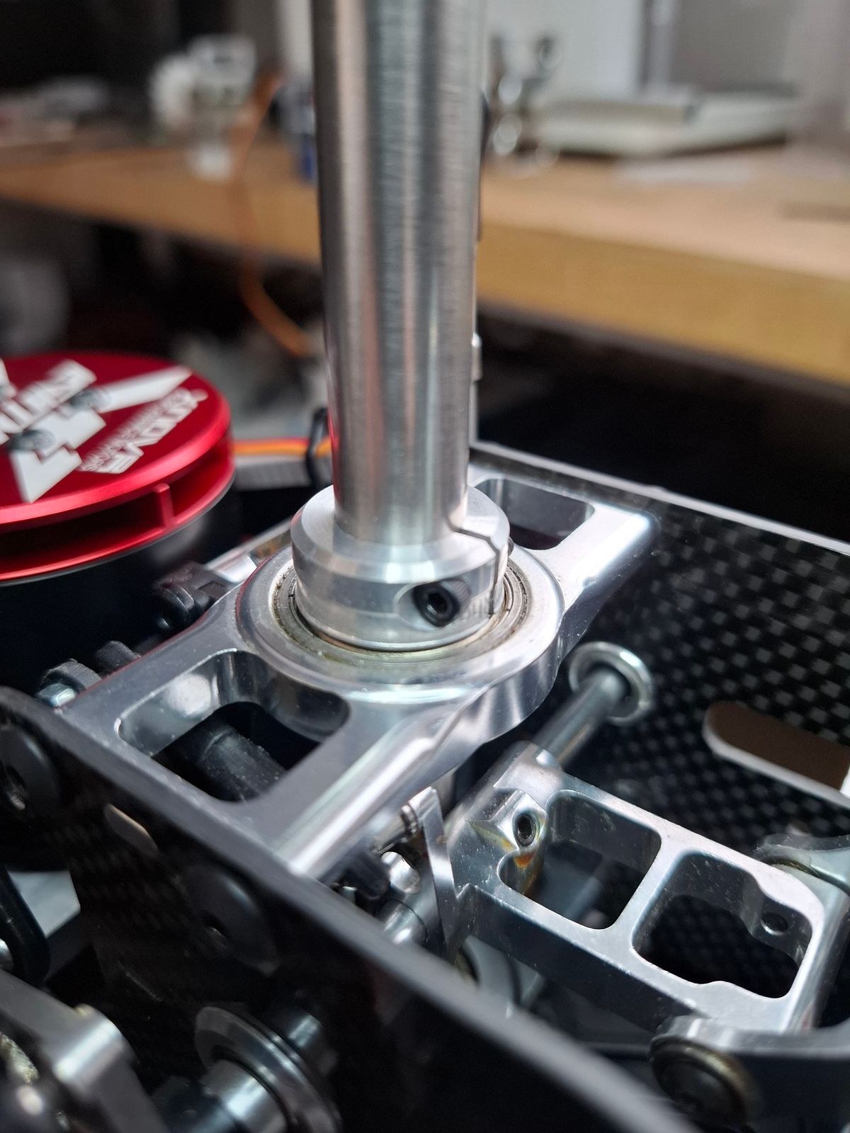
Clamp ring for main shaft
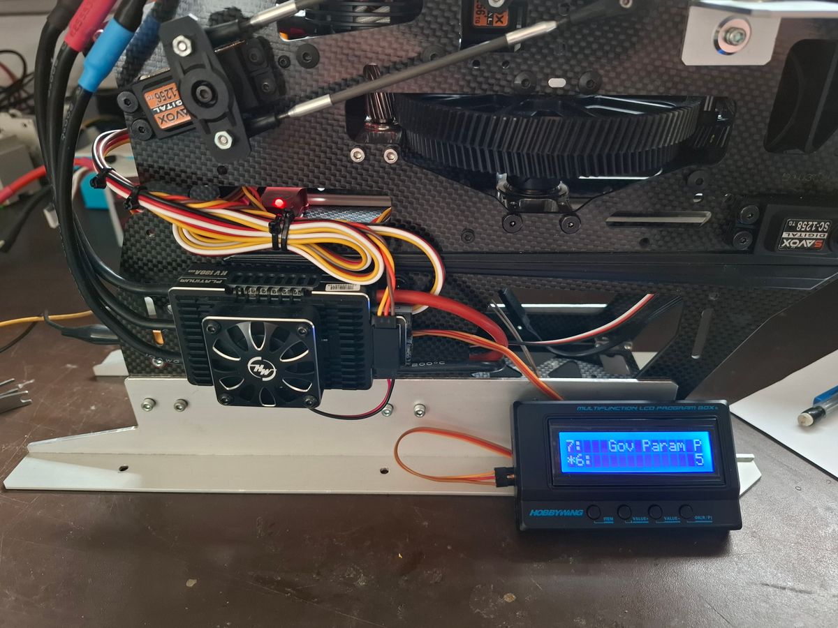
ESC radio setup
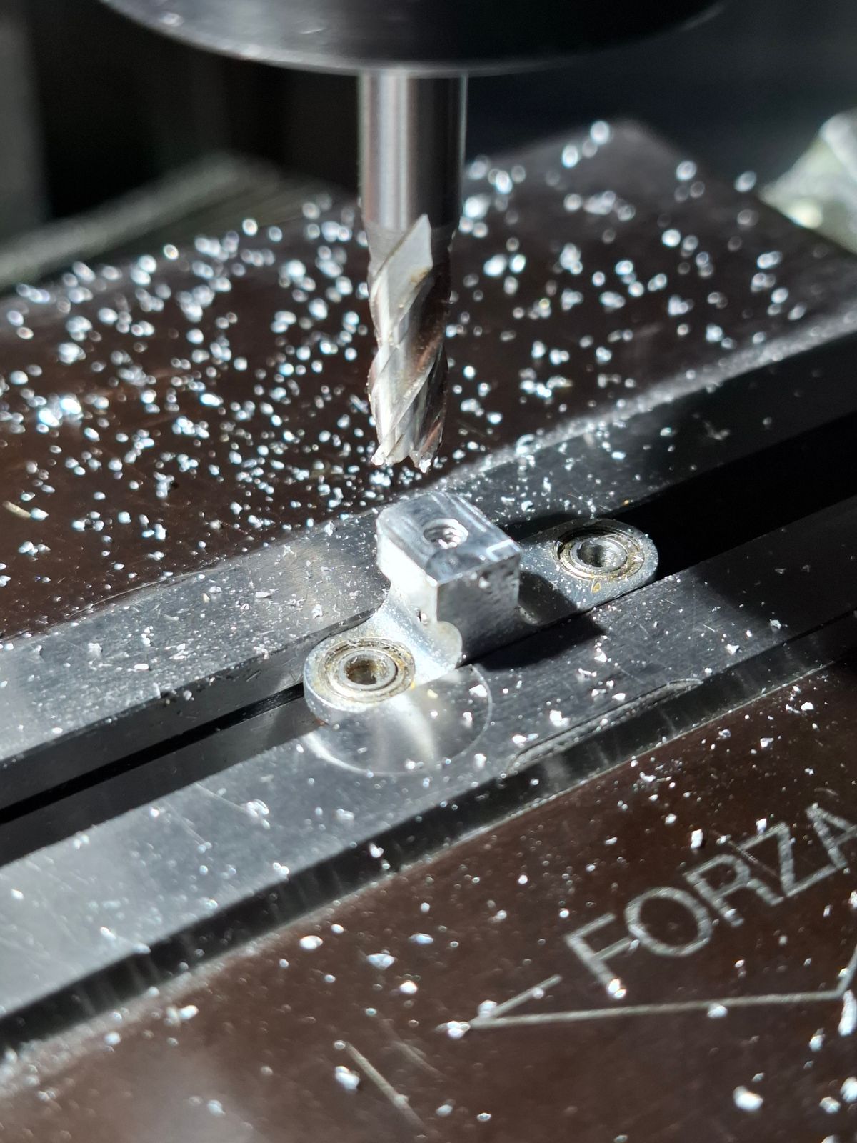
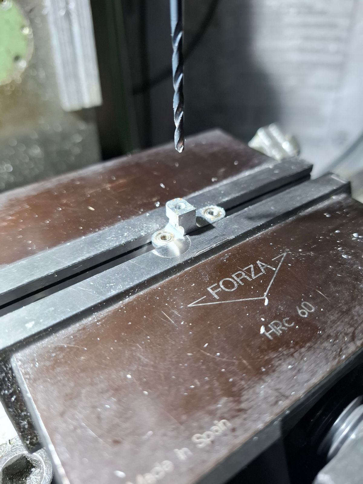
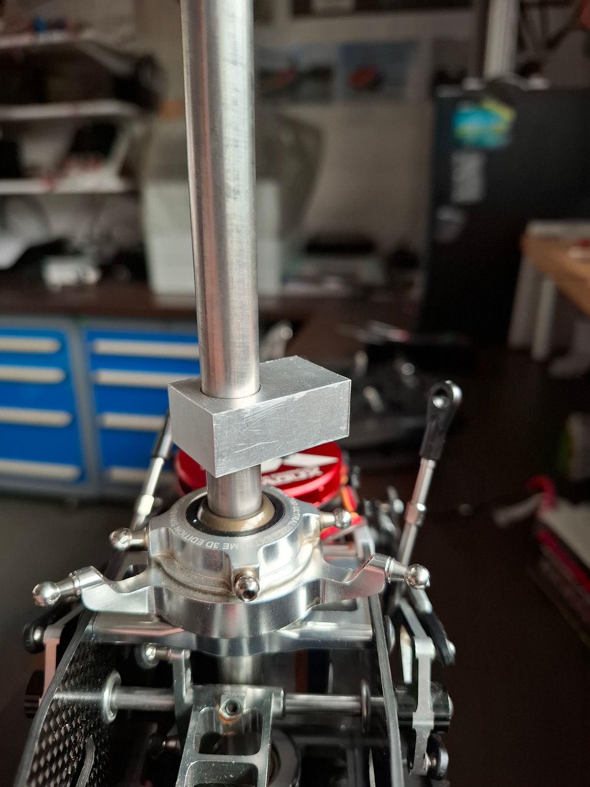
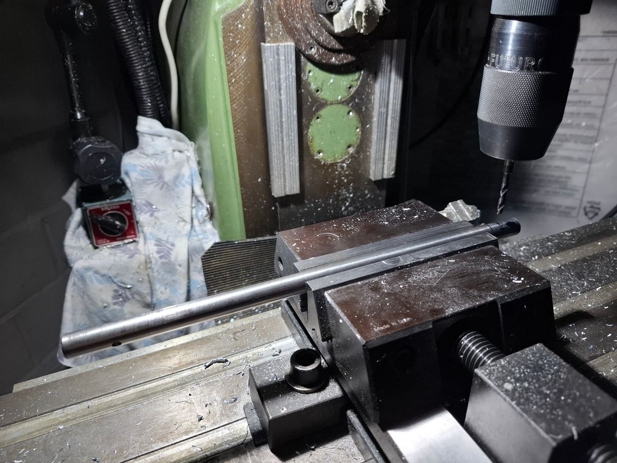
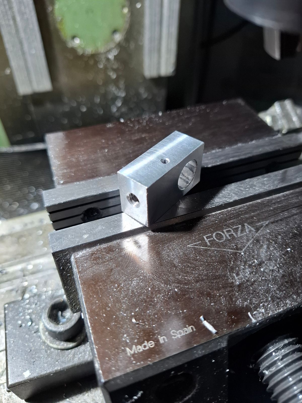
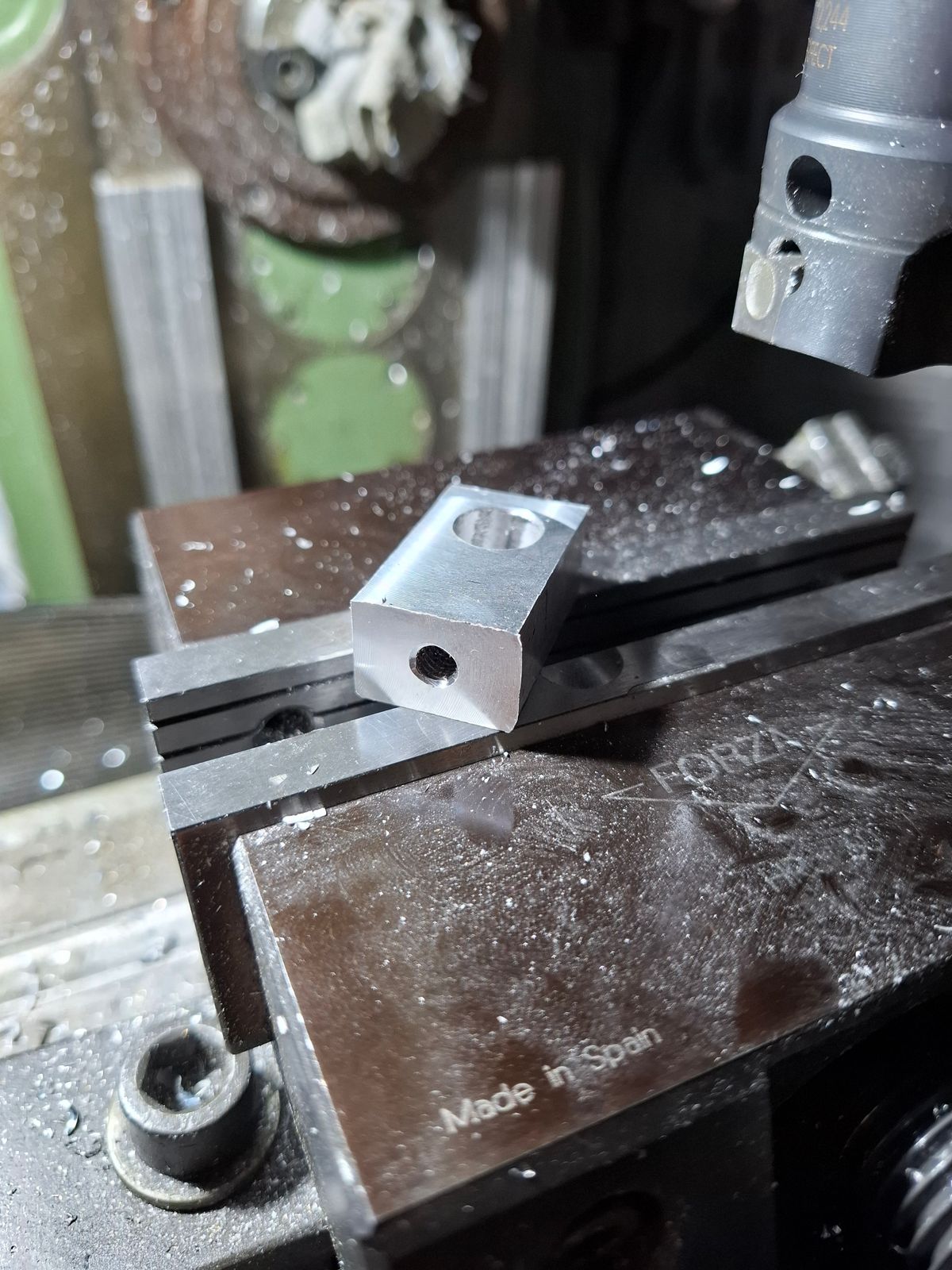
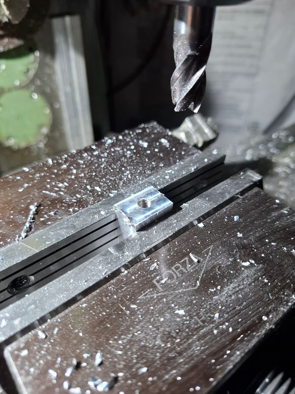
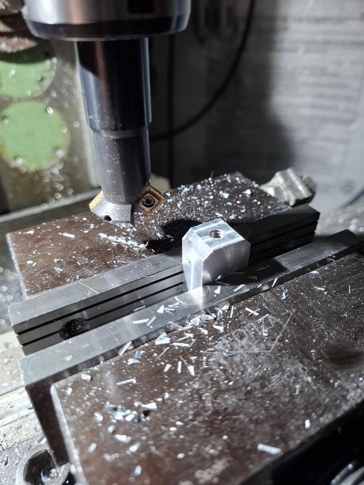
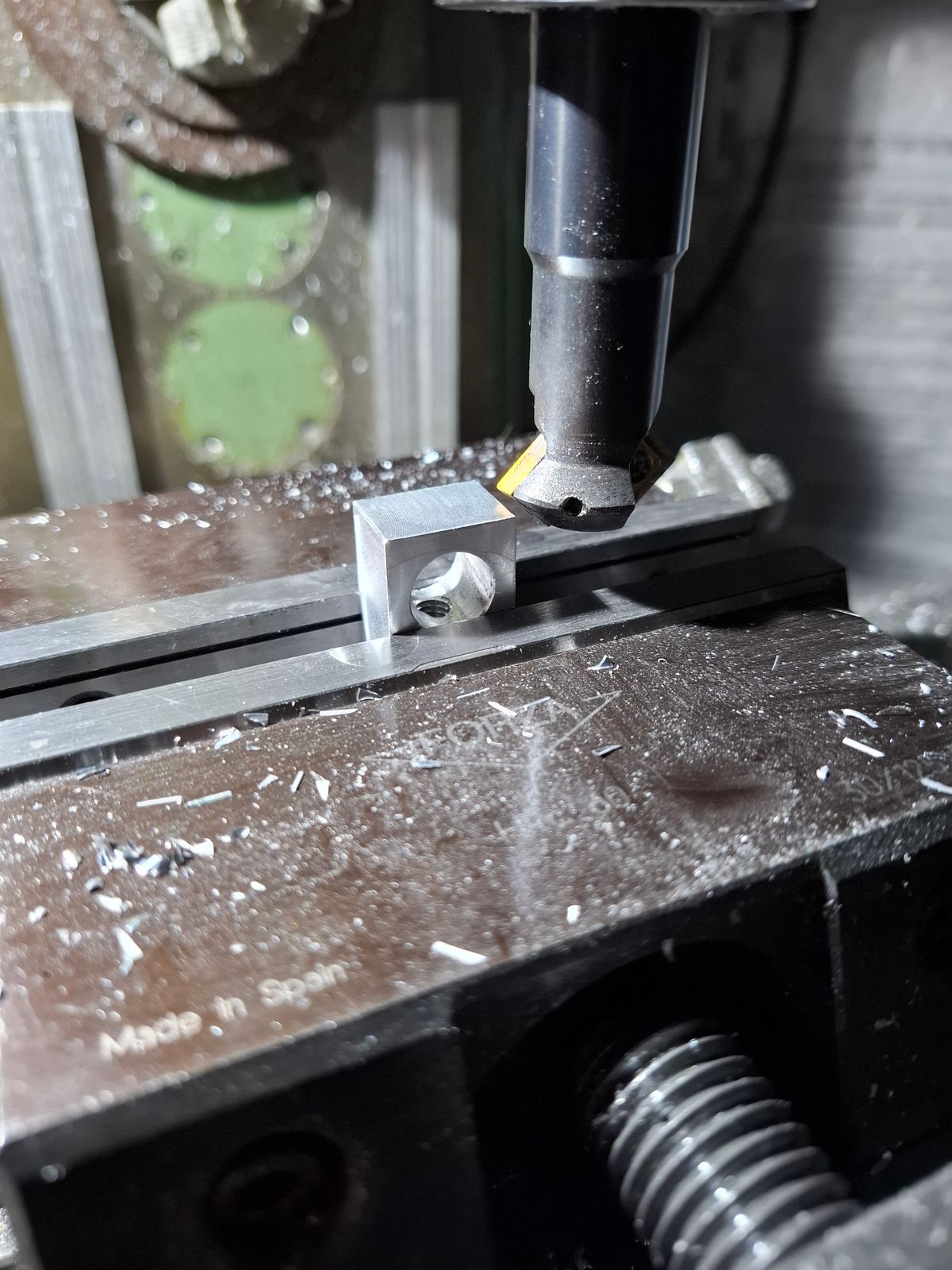
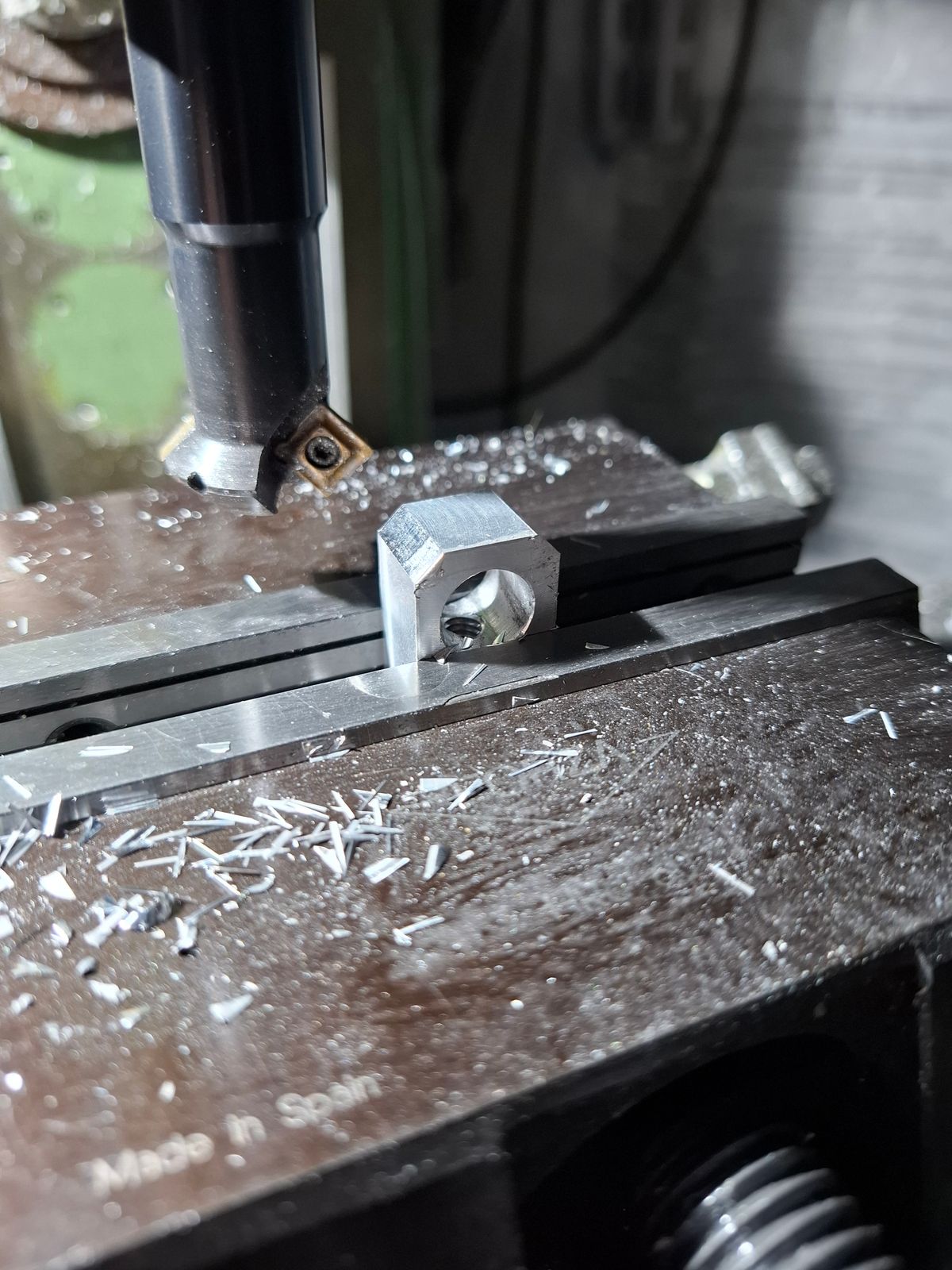
Milling central part for swashplate follower.
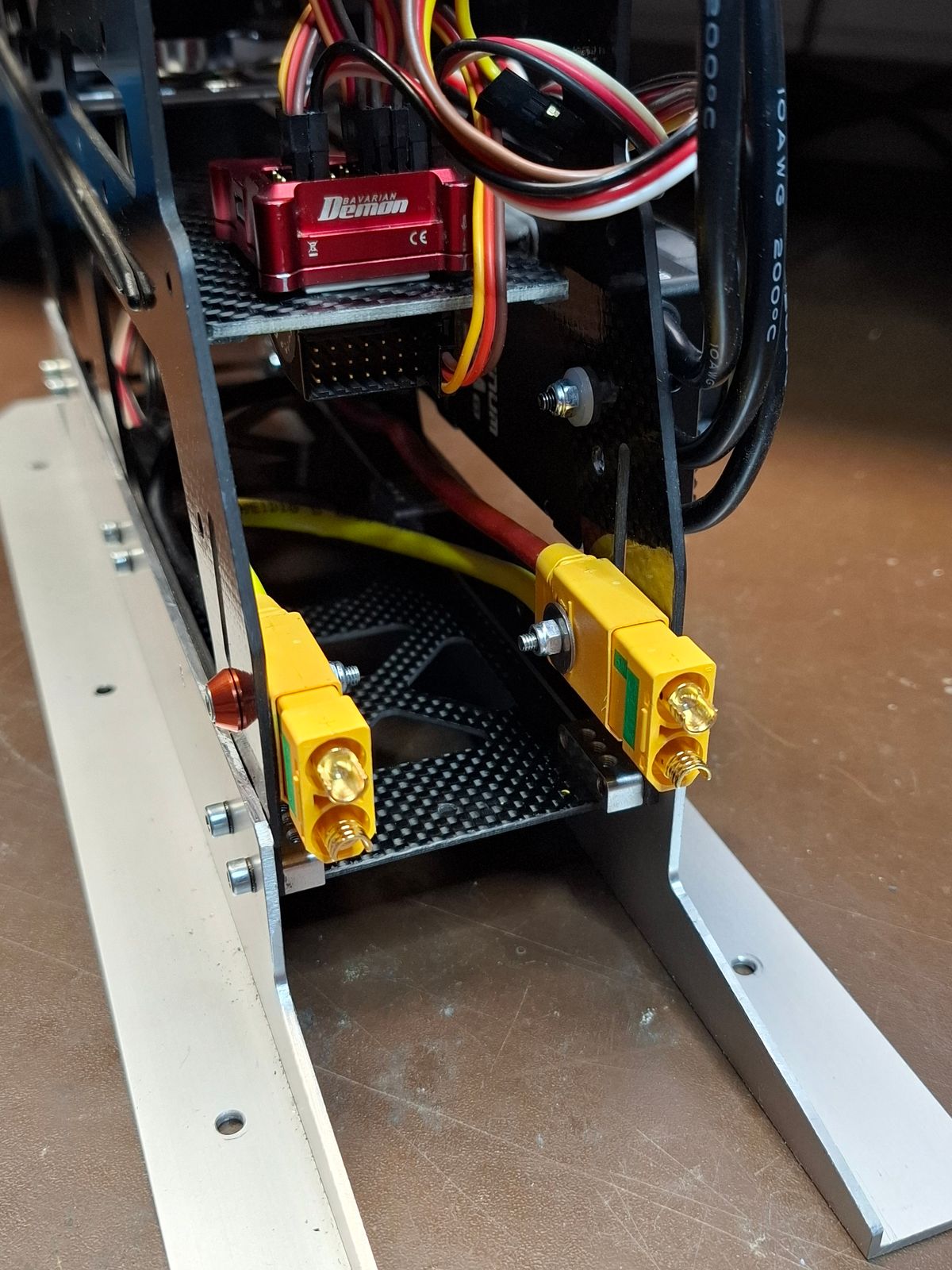
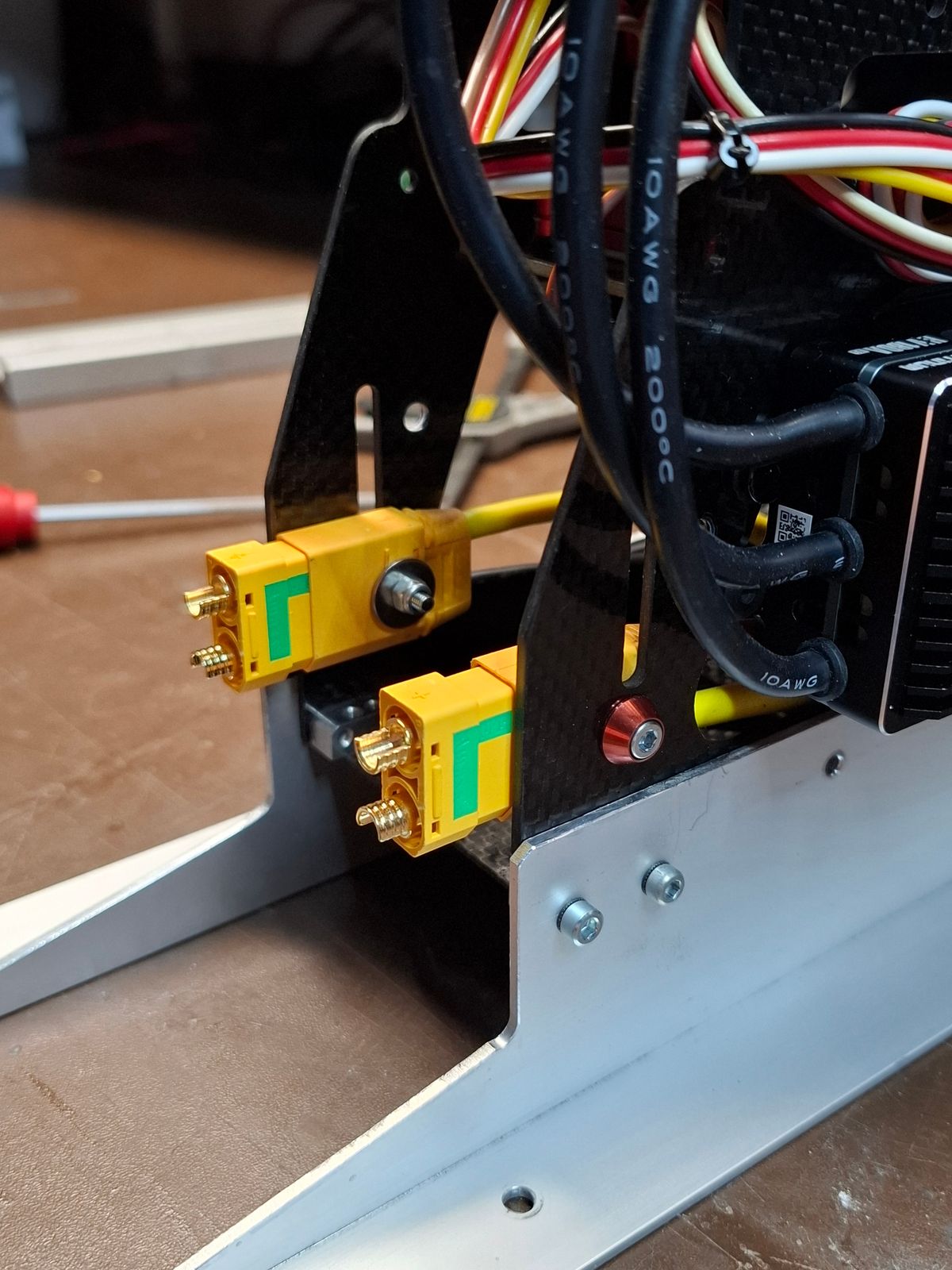
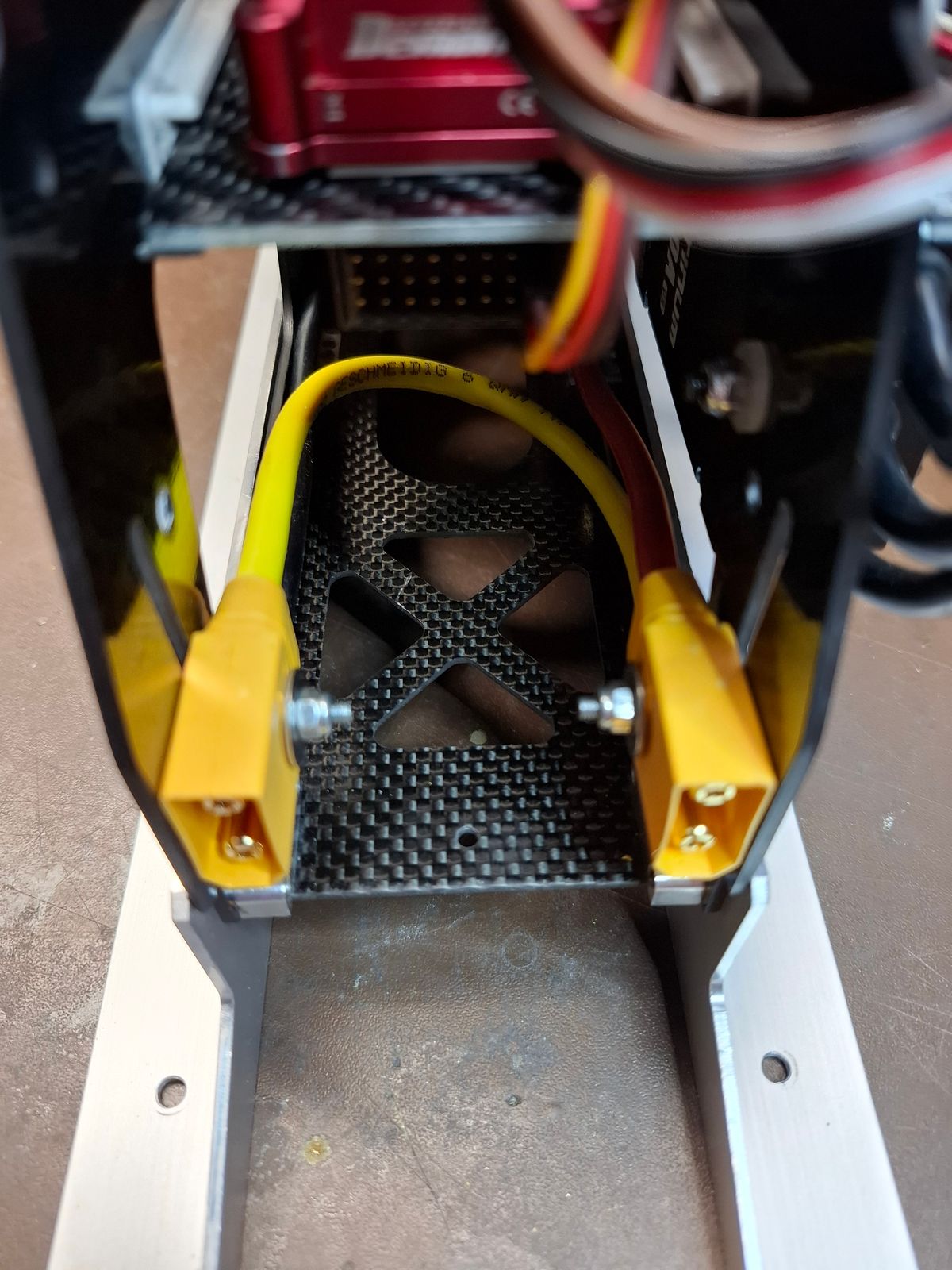
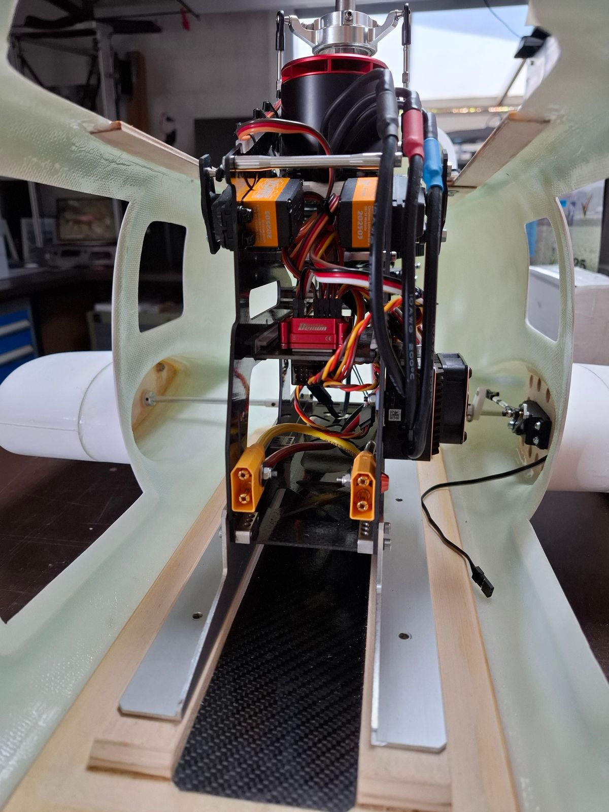
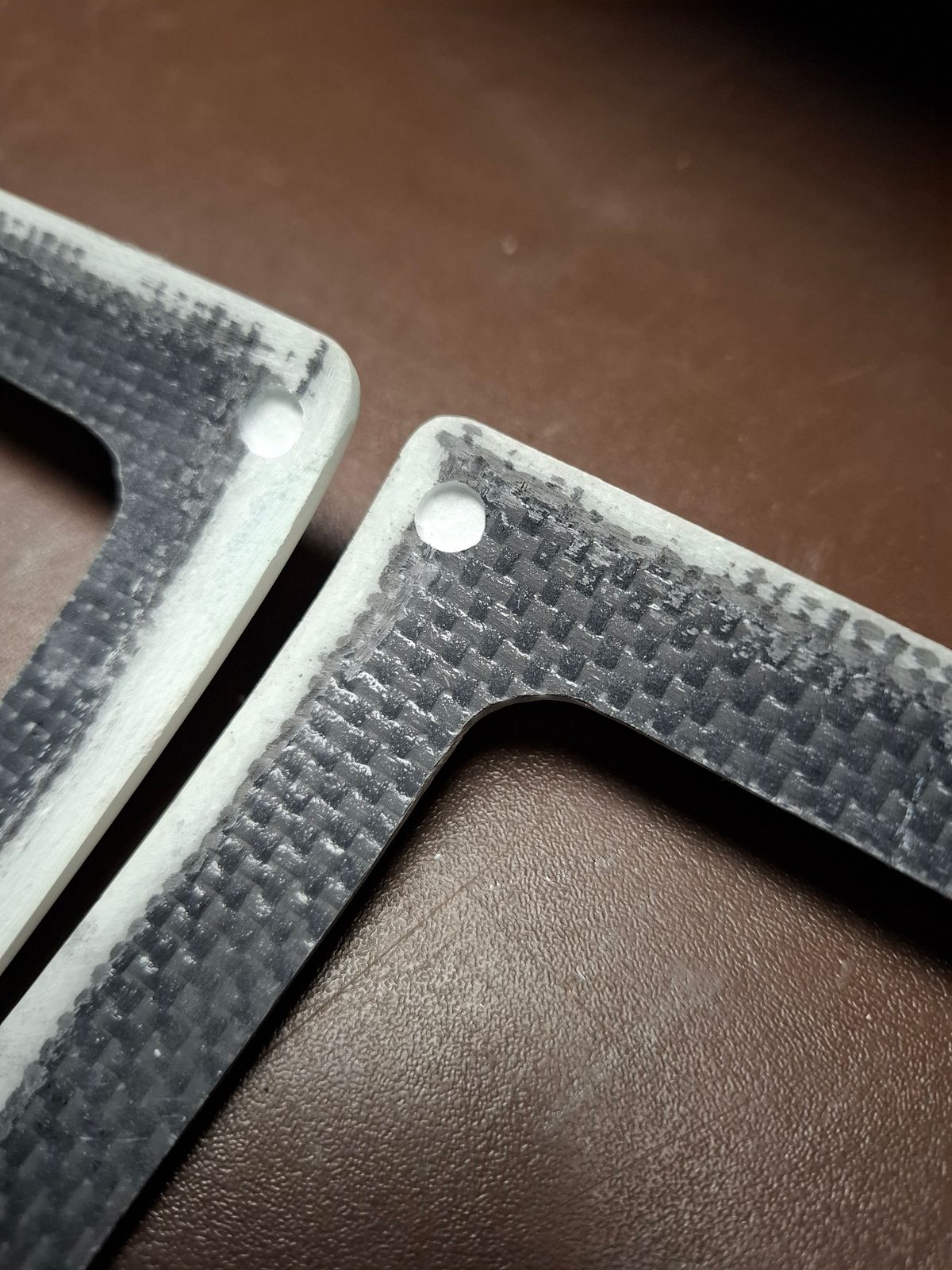
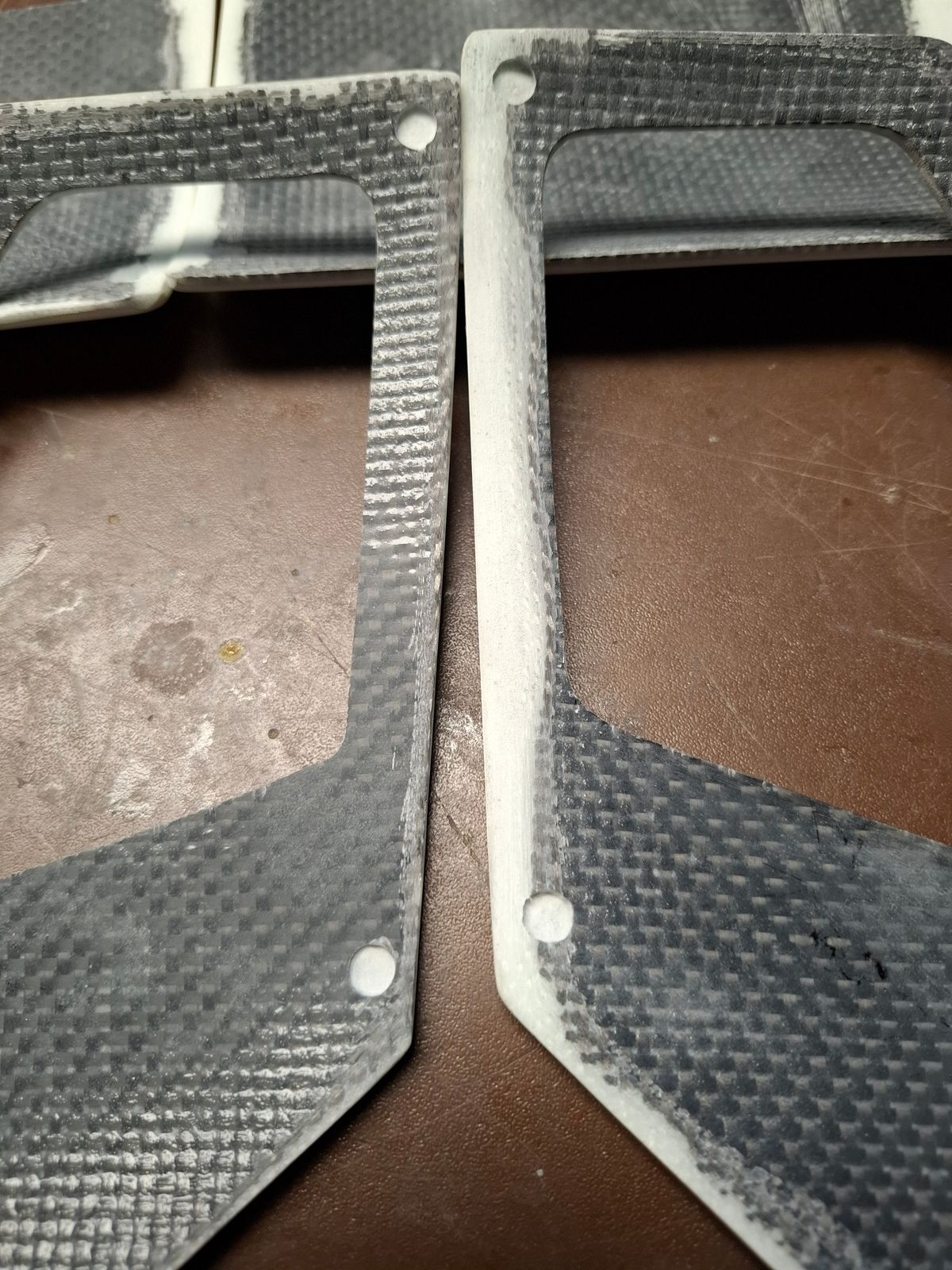
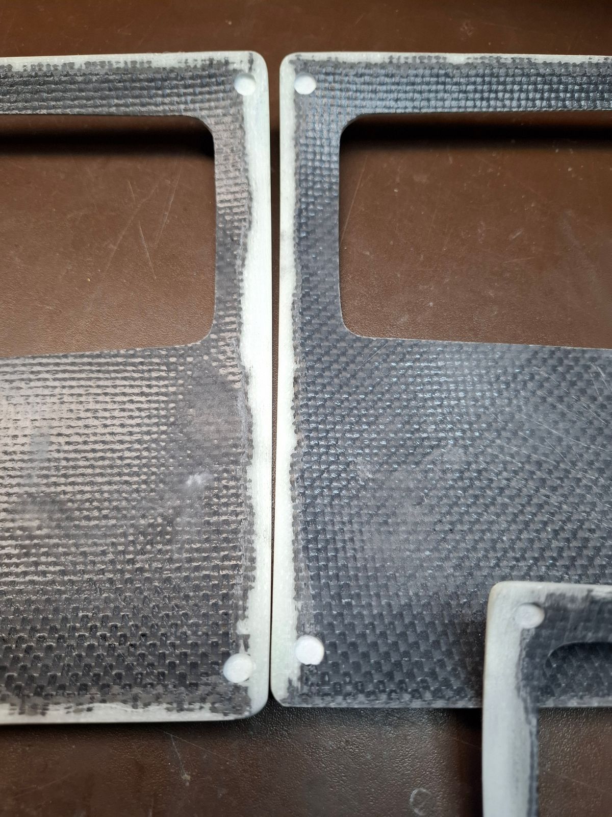
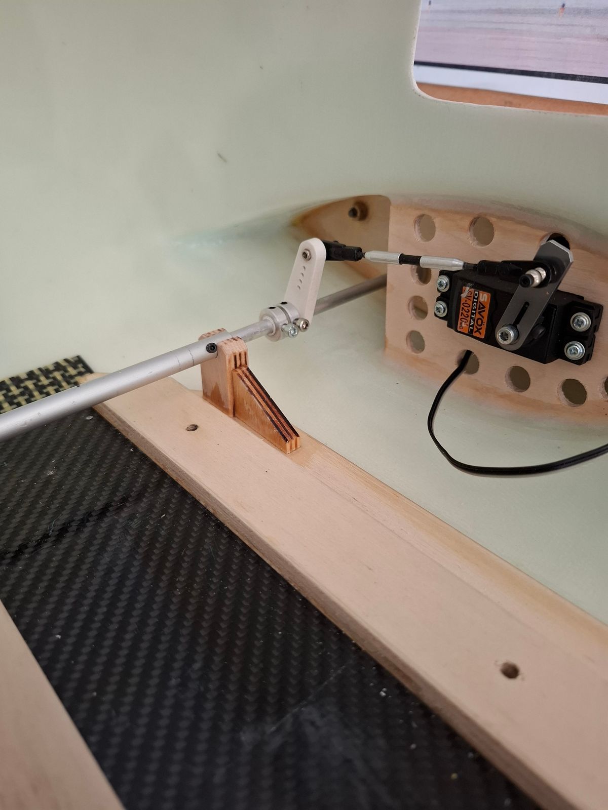
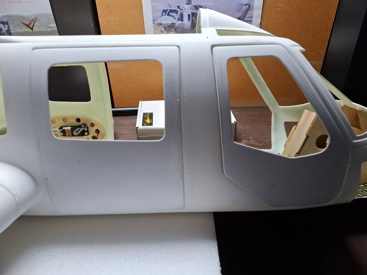
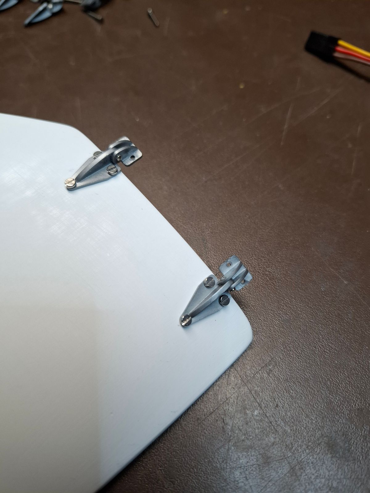
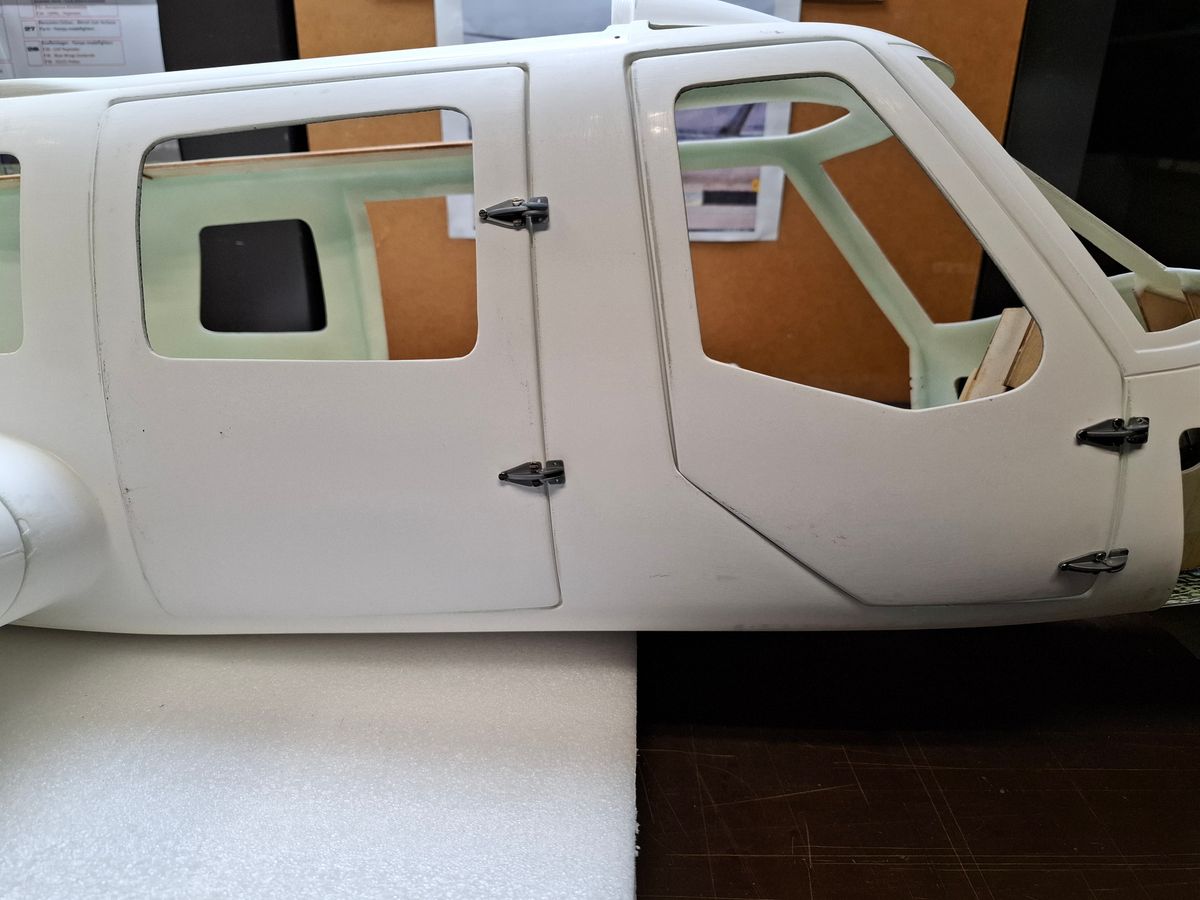
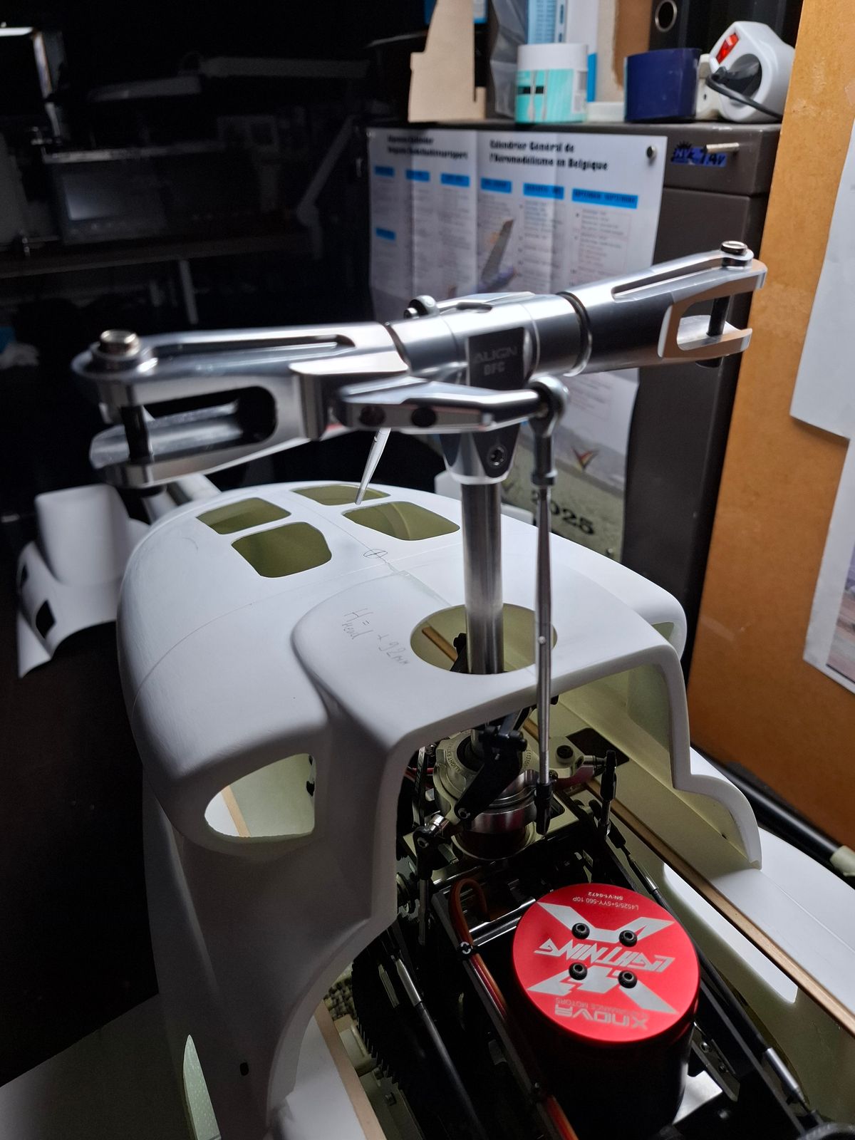
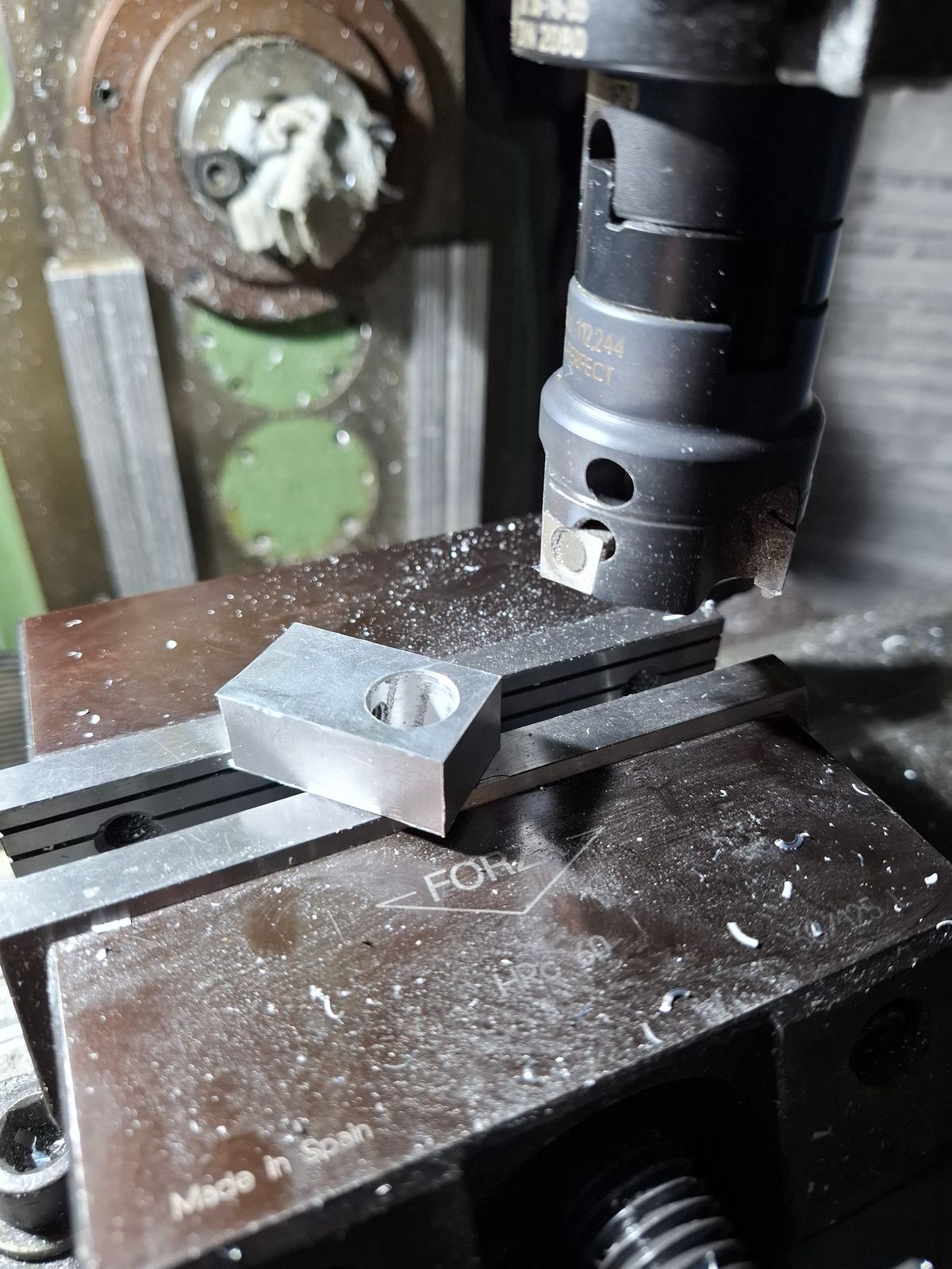
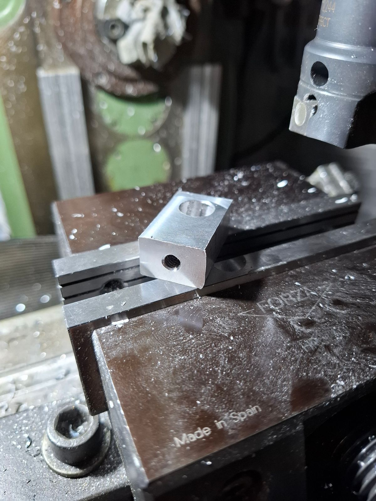
Some machining...
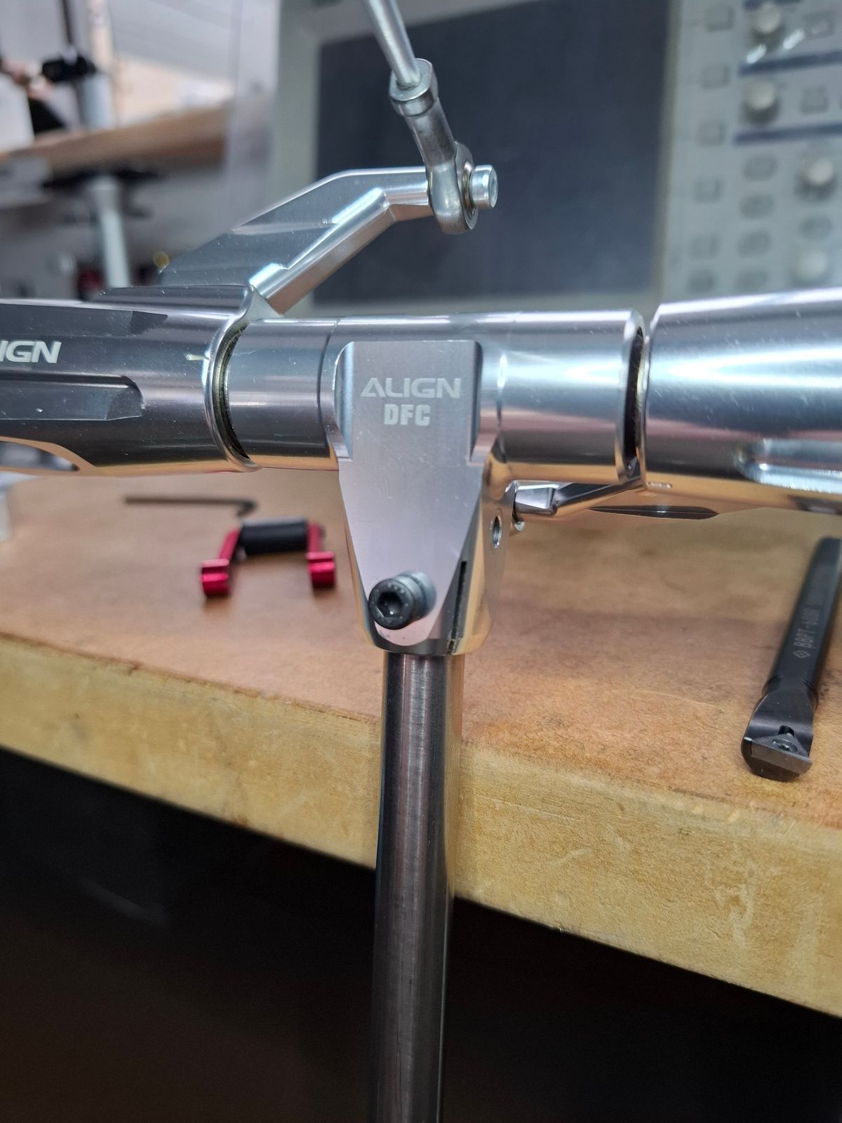
Stainless steel main shaft finishing
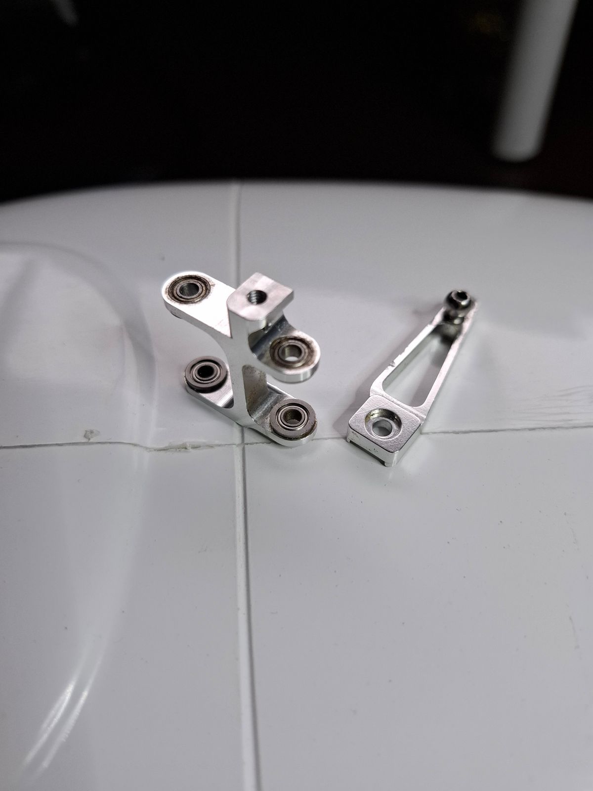
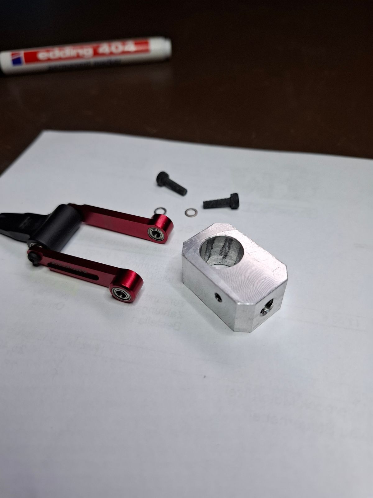
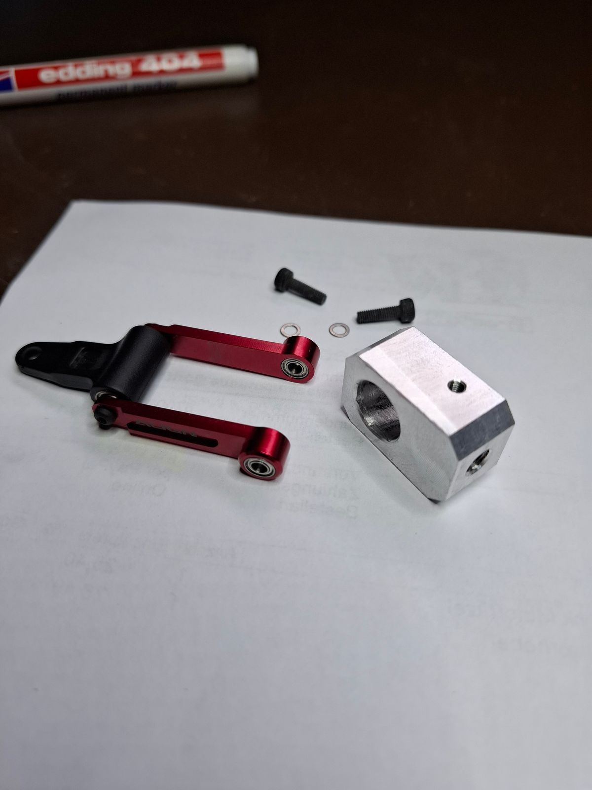
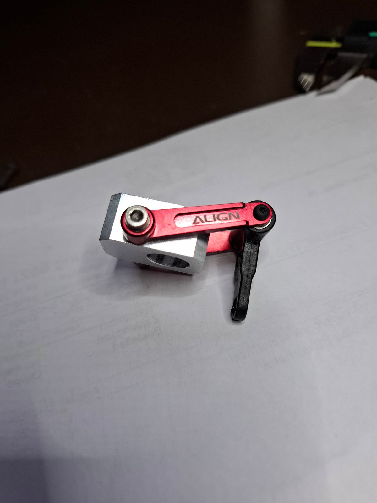
Machining swashplate follower
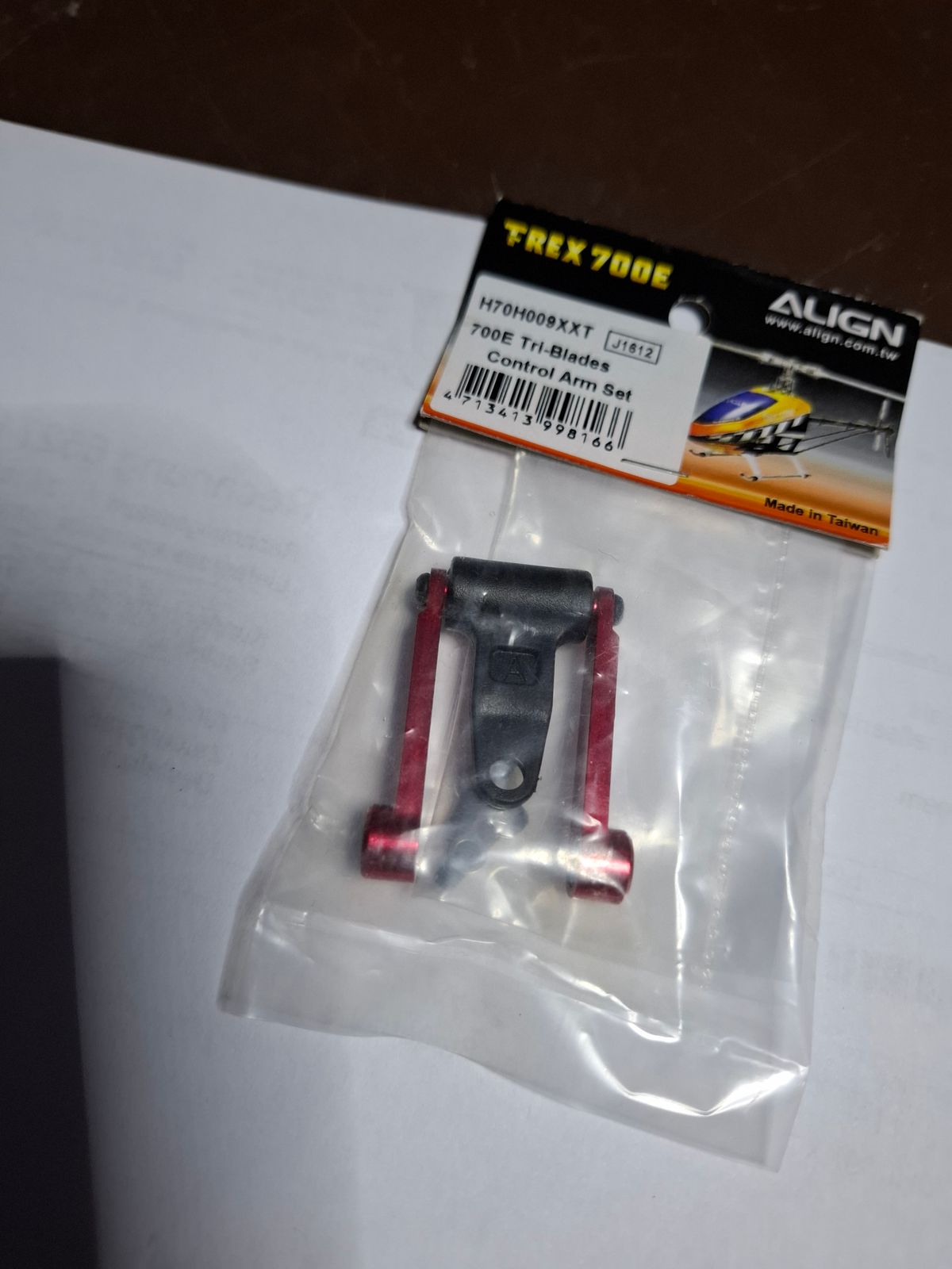
Align tri blade head control arm was used.
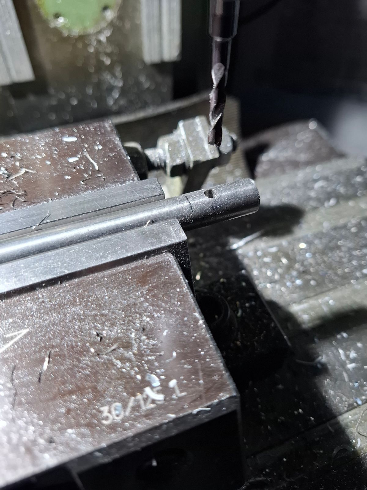
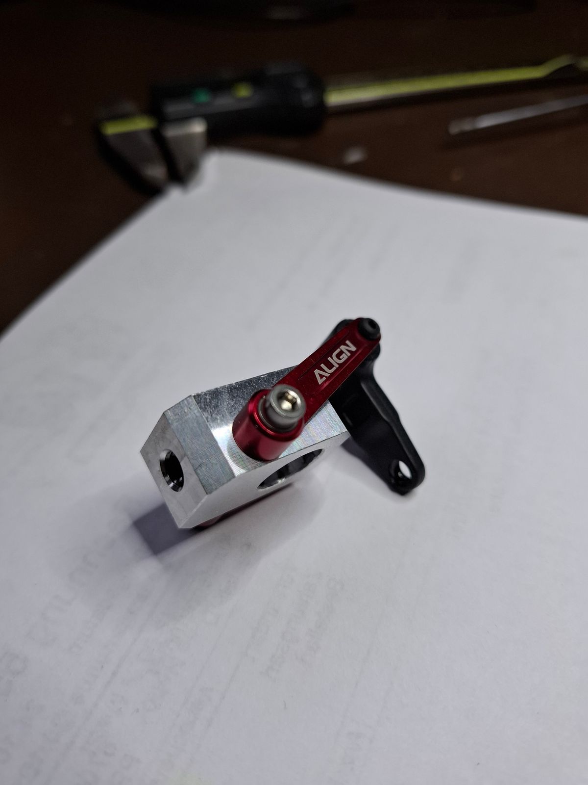
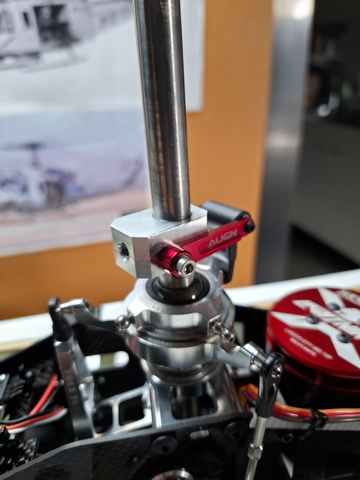
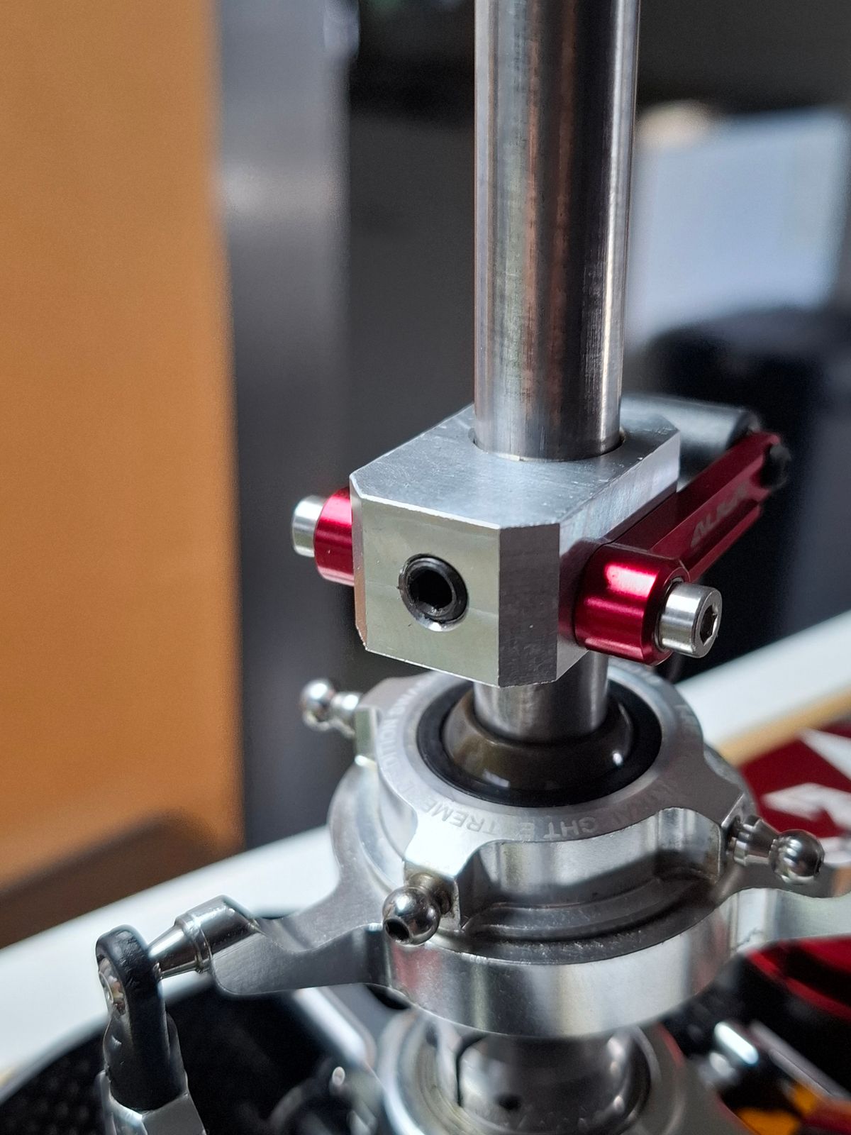
Modifications and improvements.
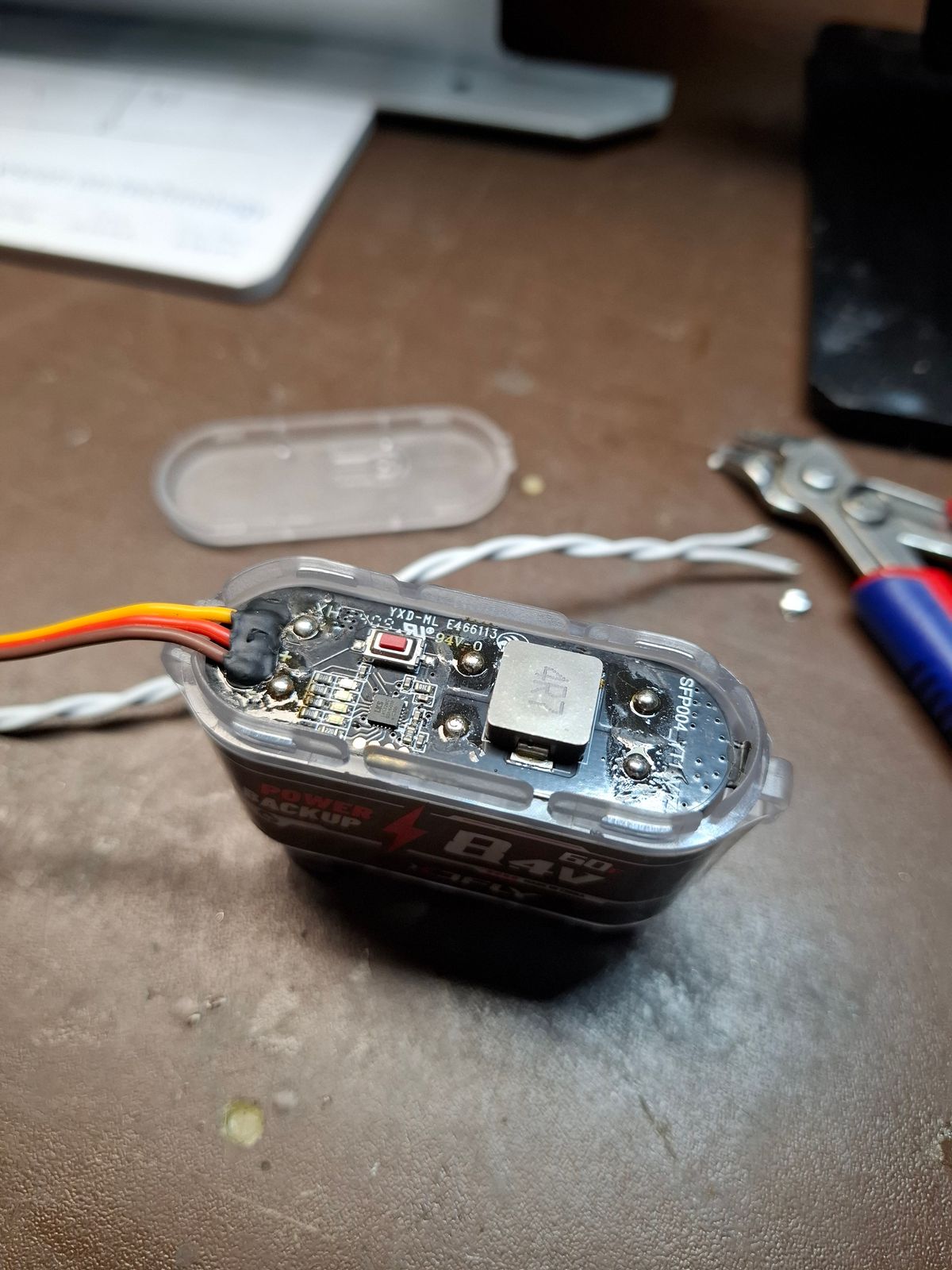
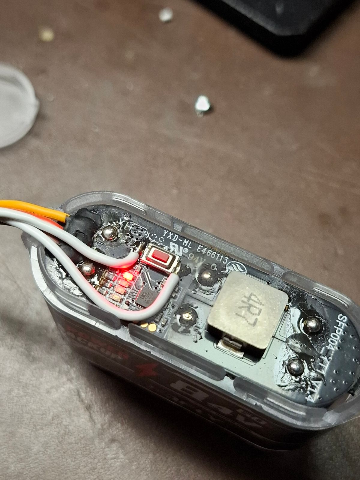
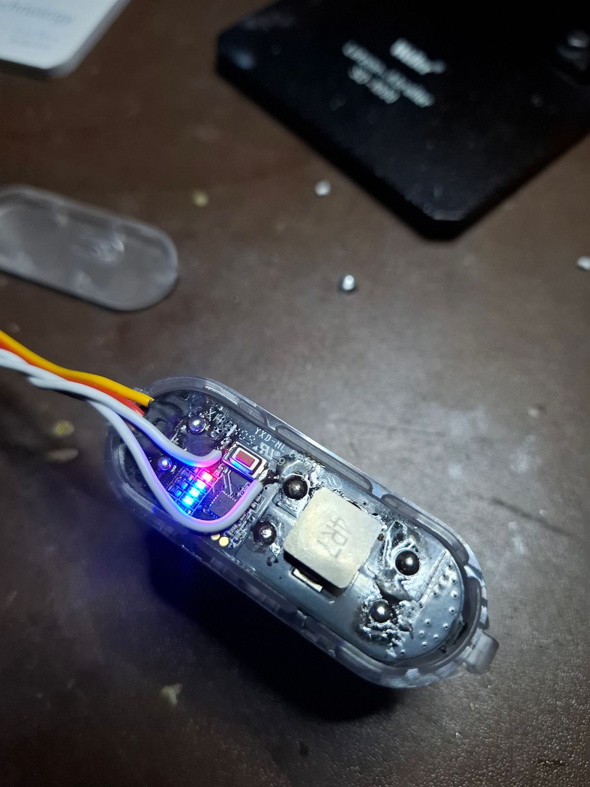
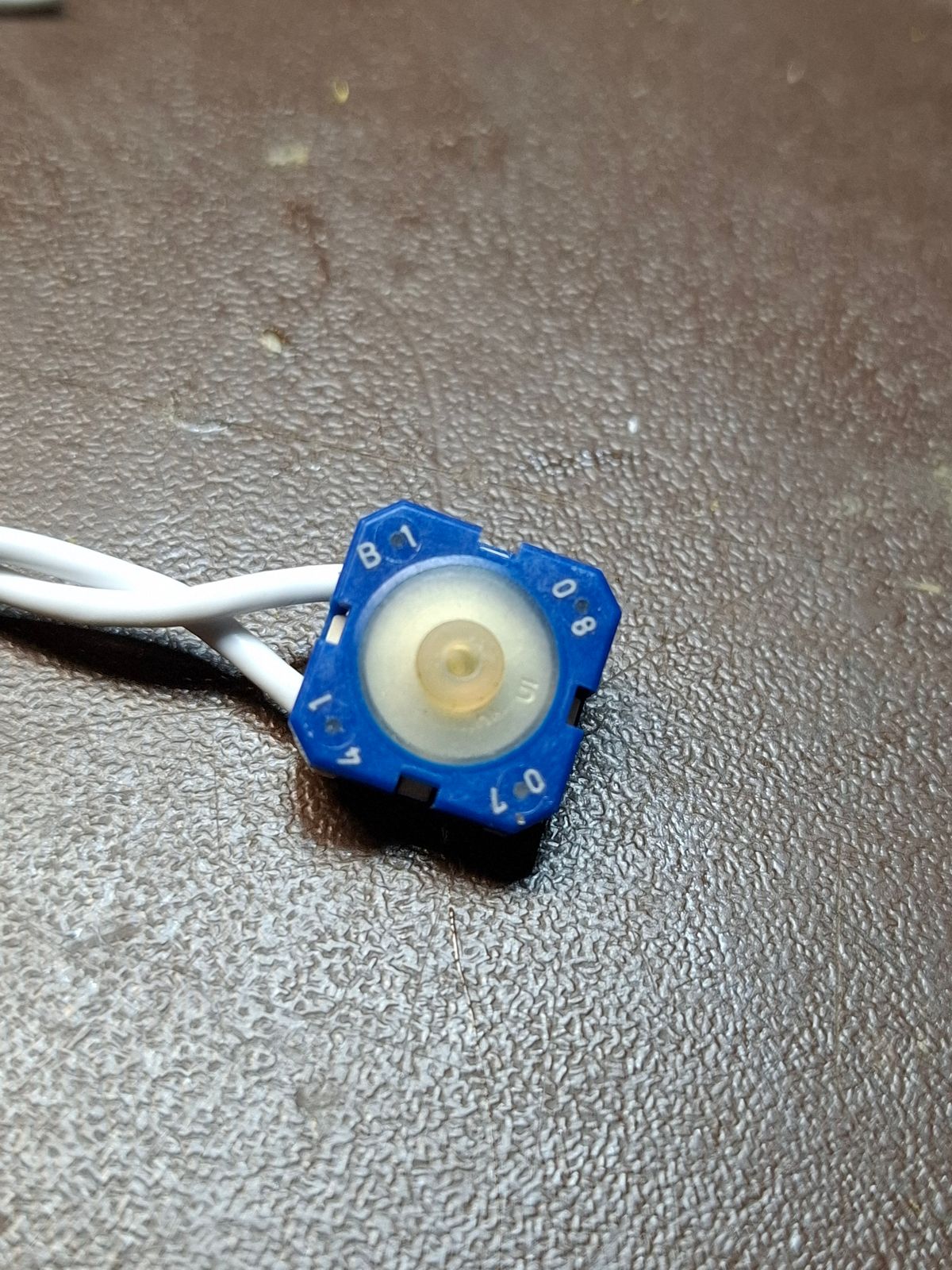
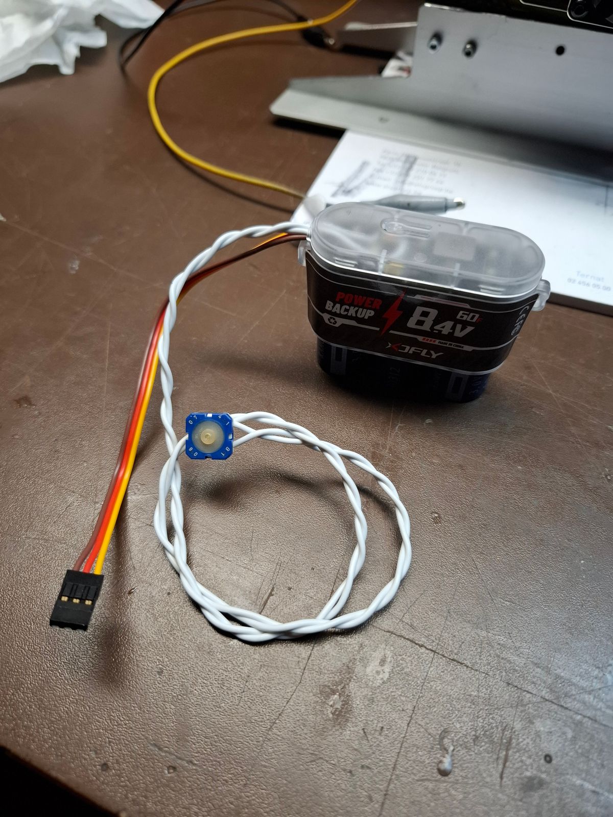
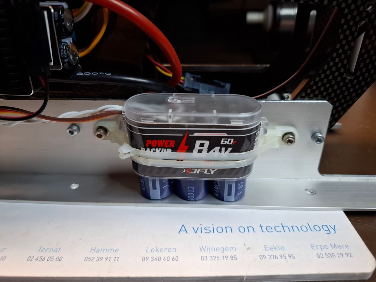
Wiring and external power off button on the Capacity buffer unit.
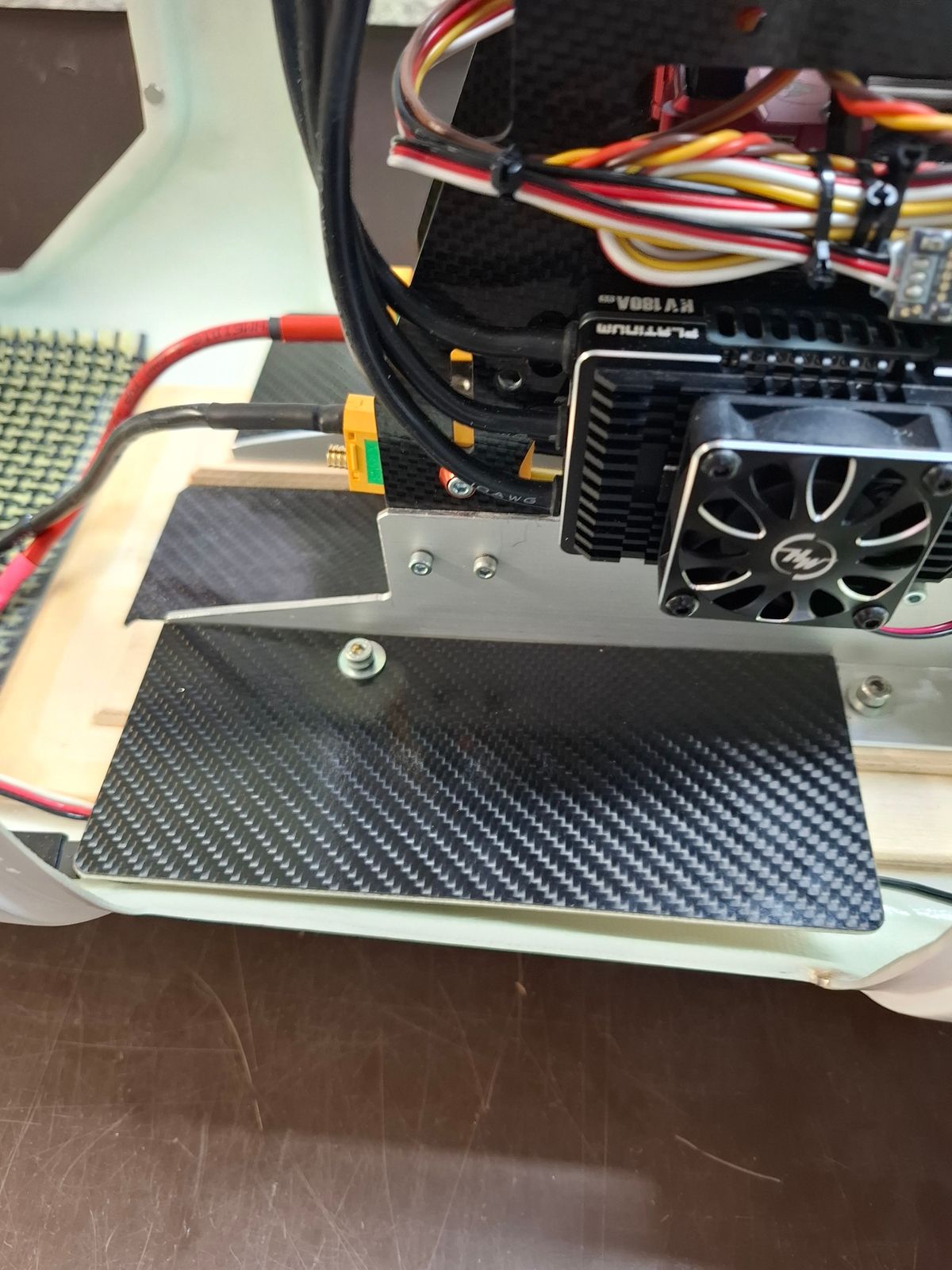
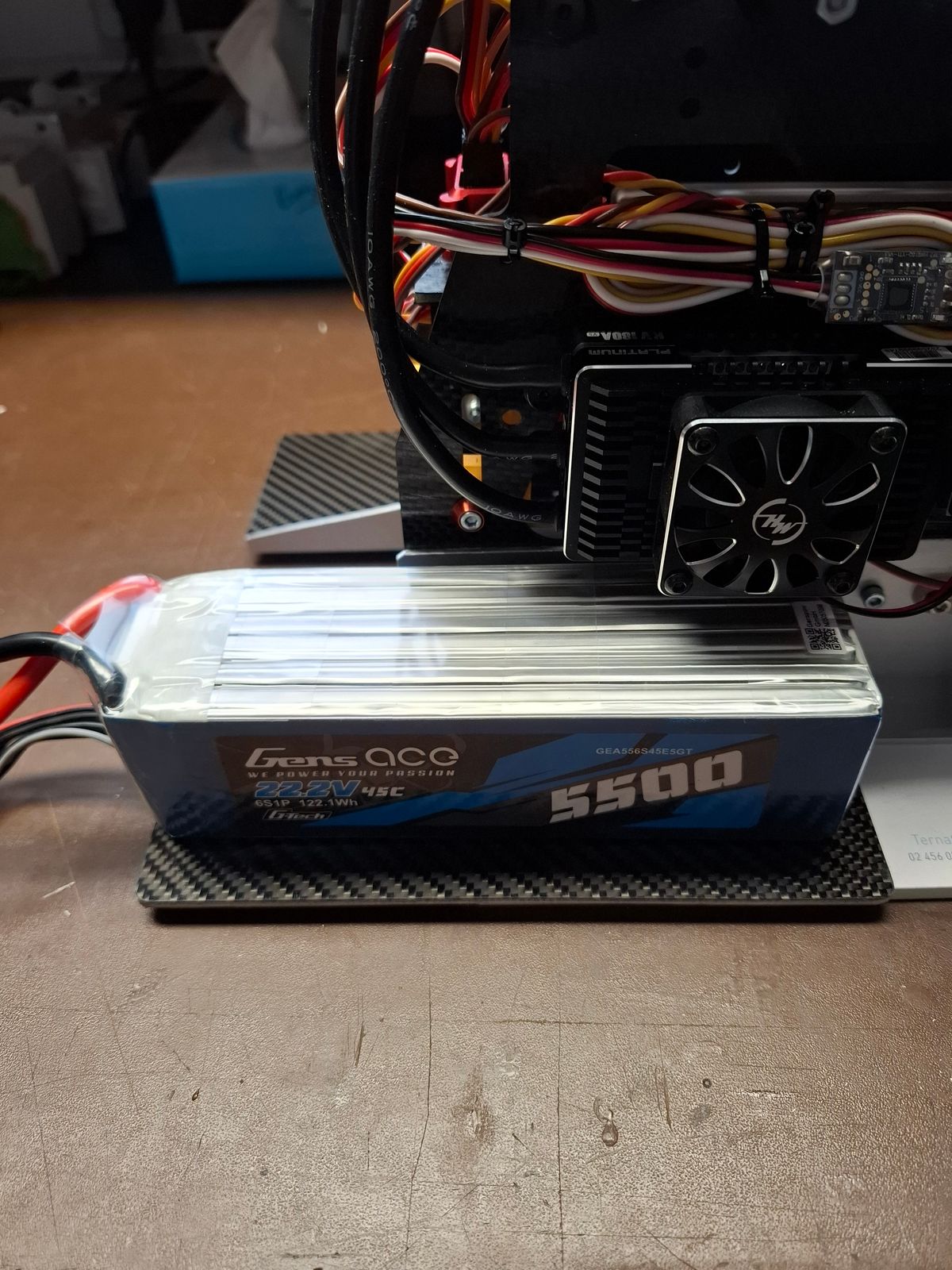
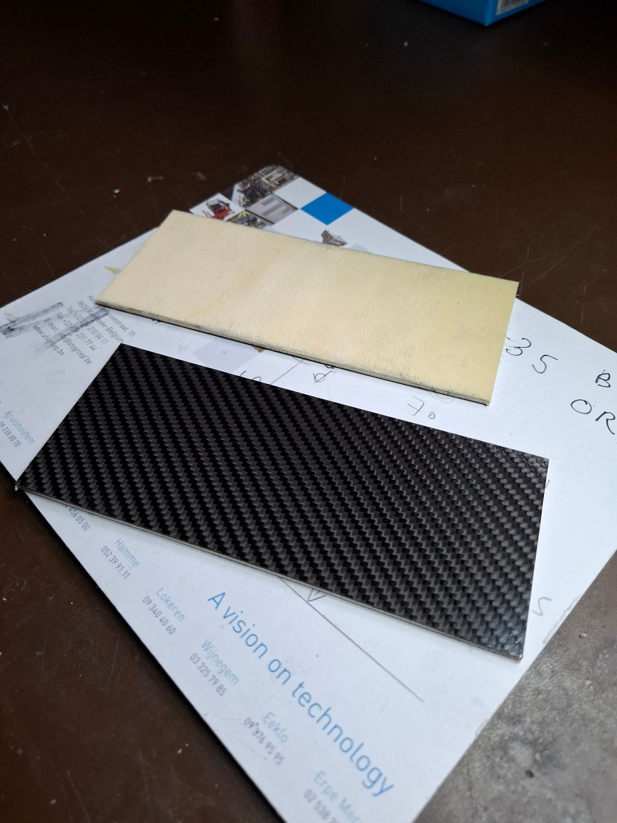
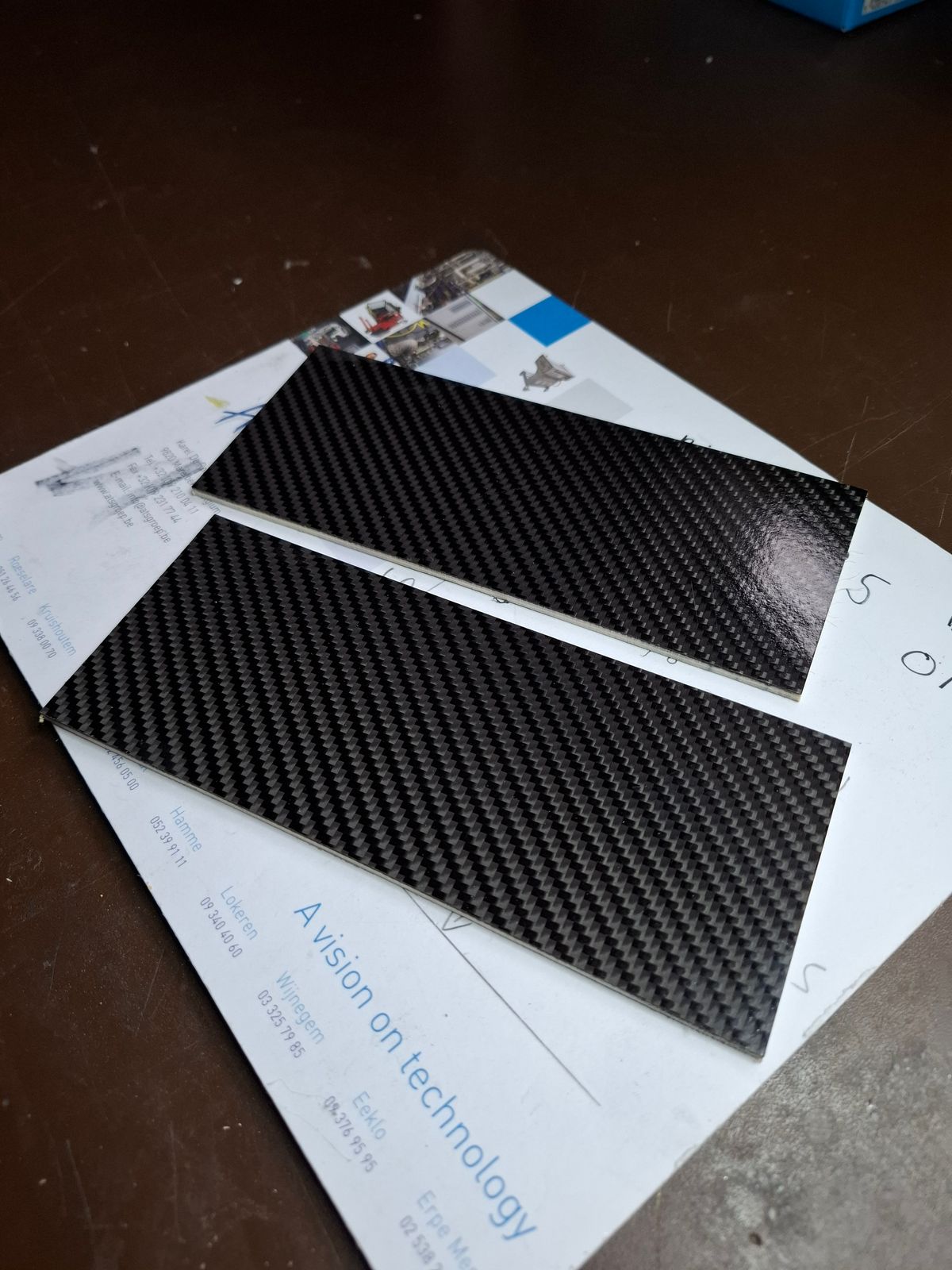
Made two lipo supporting plates, wood reinforced with a thin carbon layer.
So the battery weight it directly taken by the alu support frame, and not he fuselage.
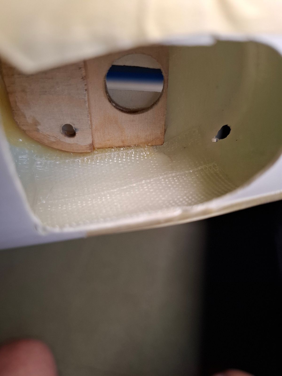
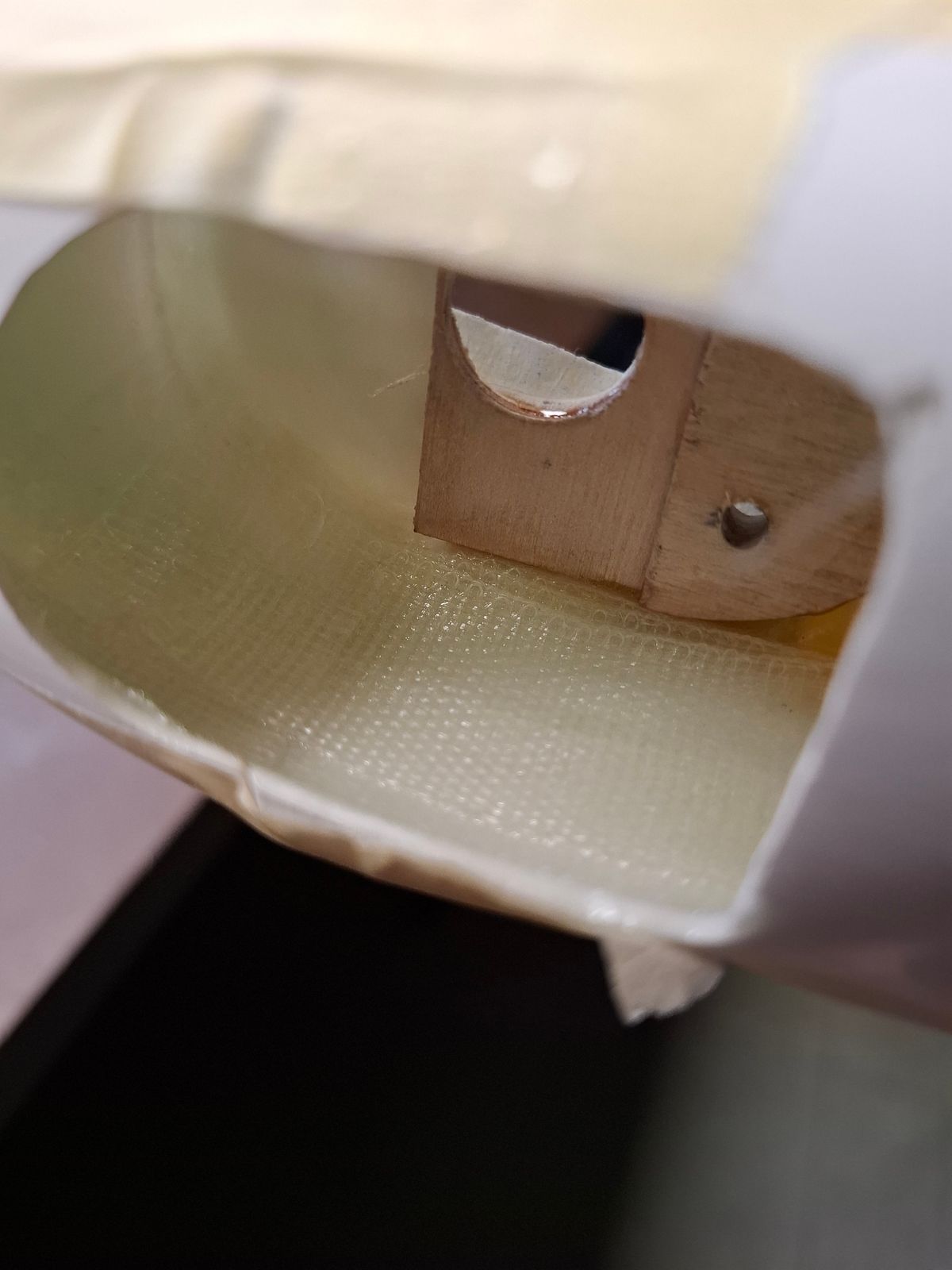
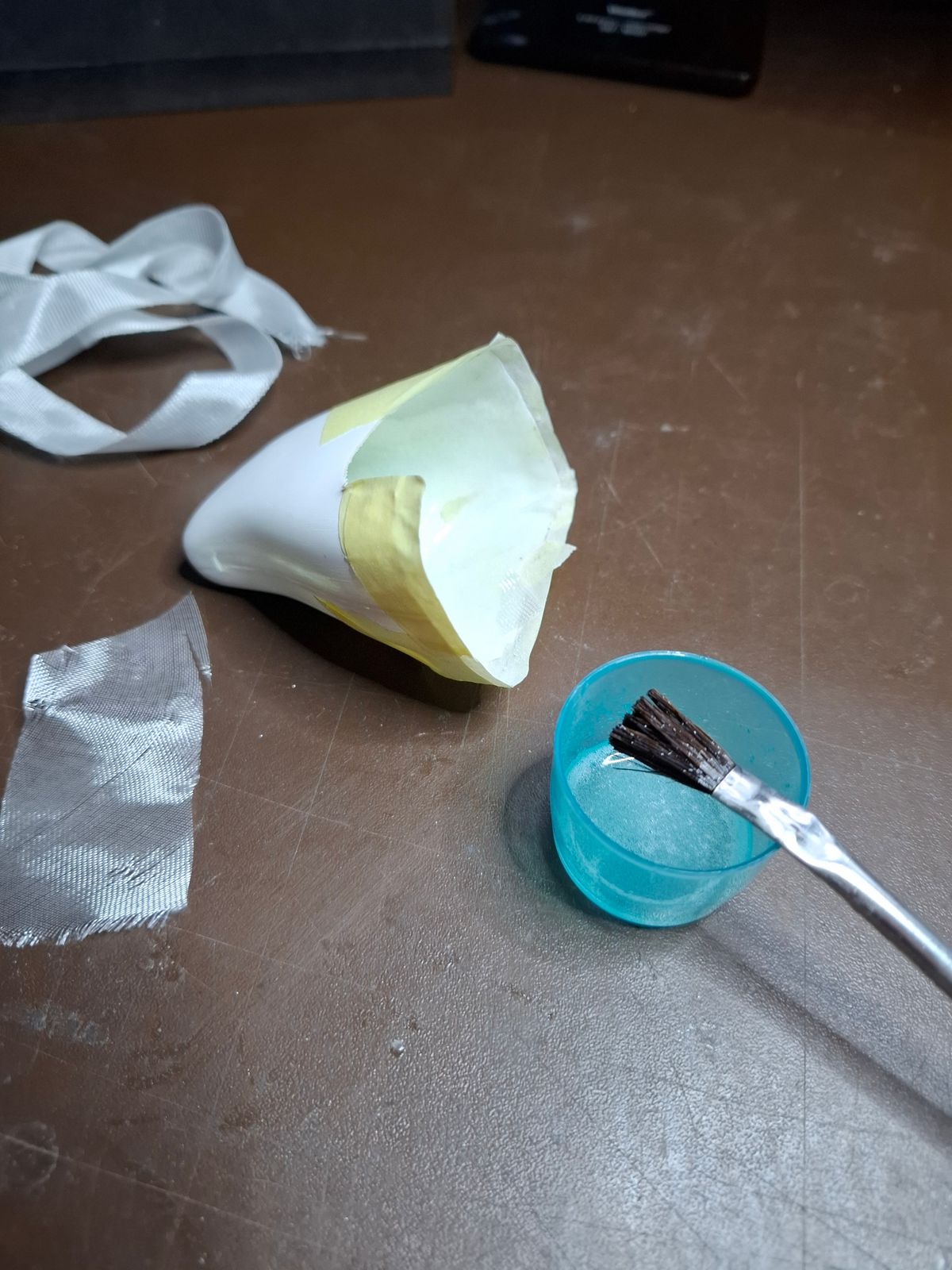
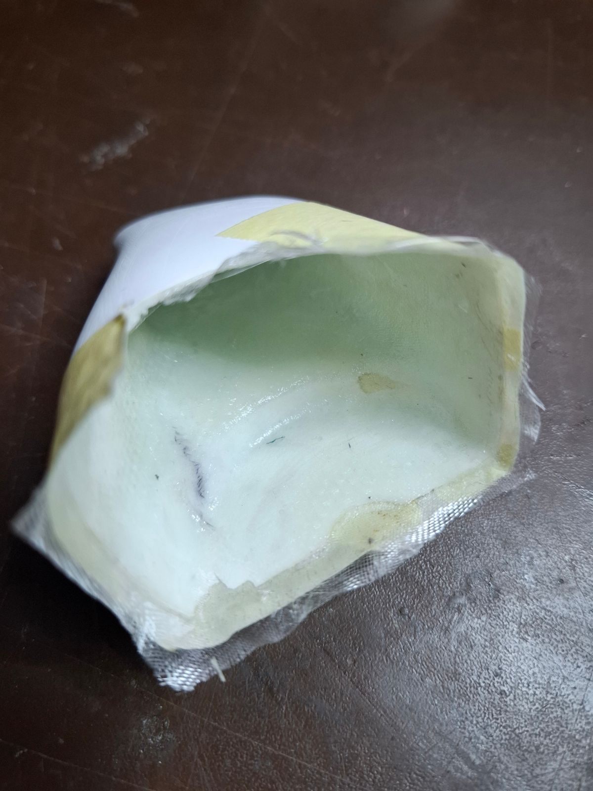
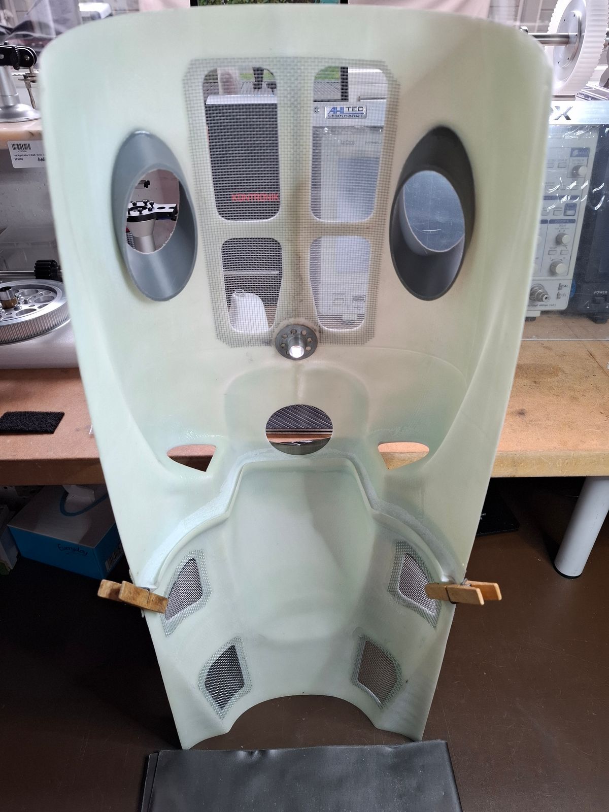
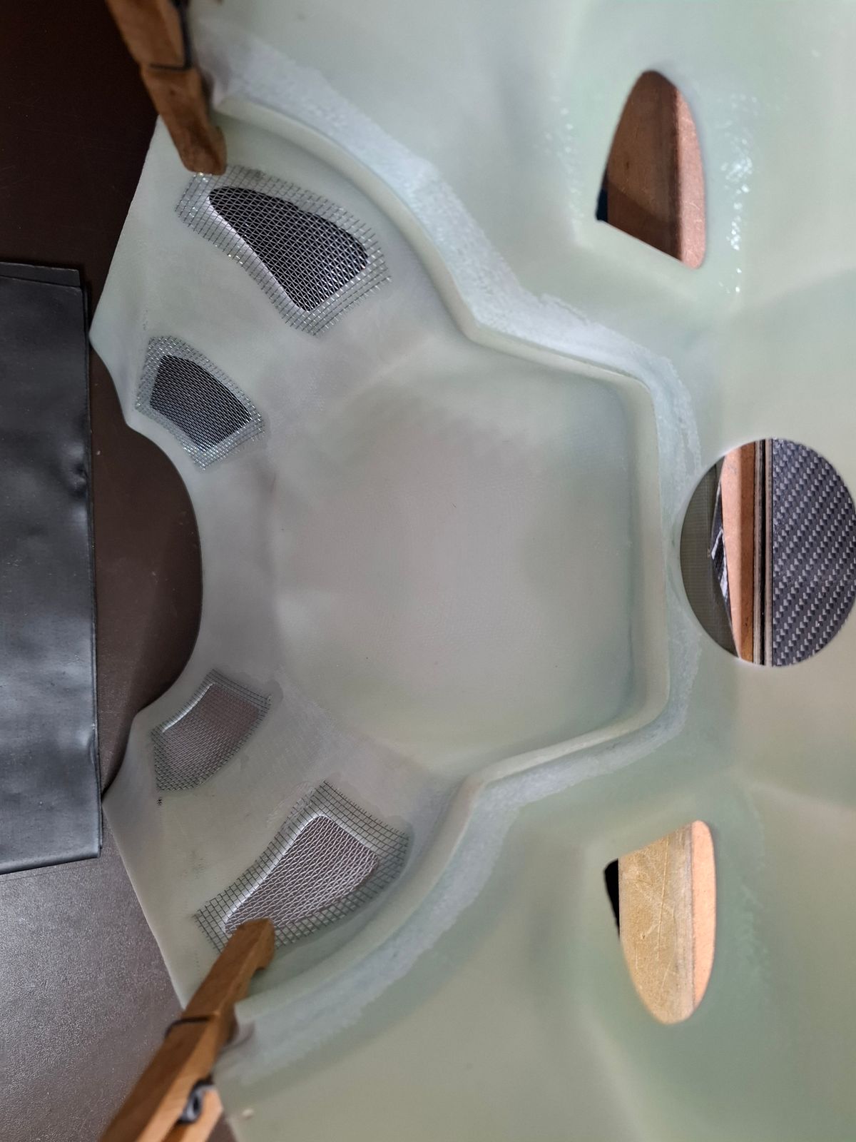
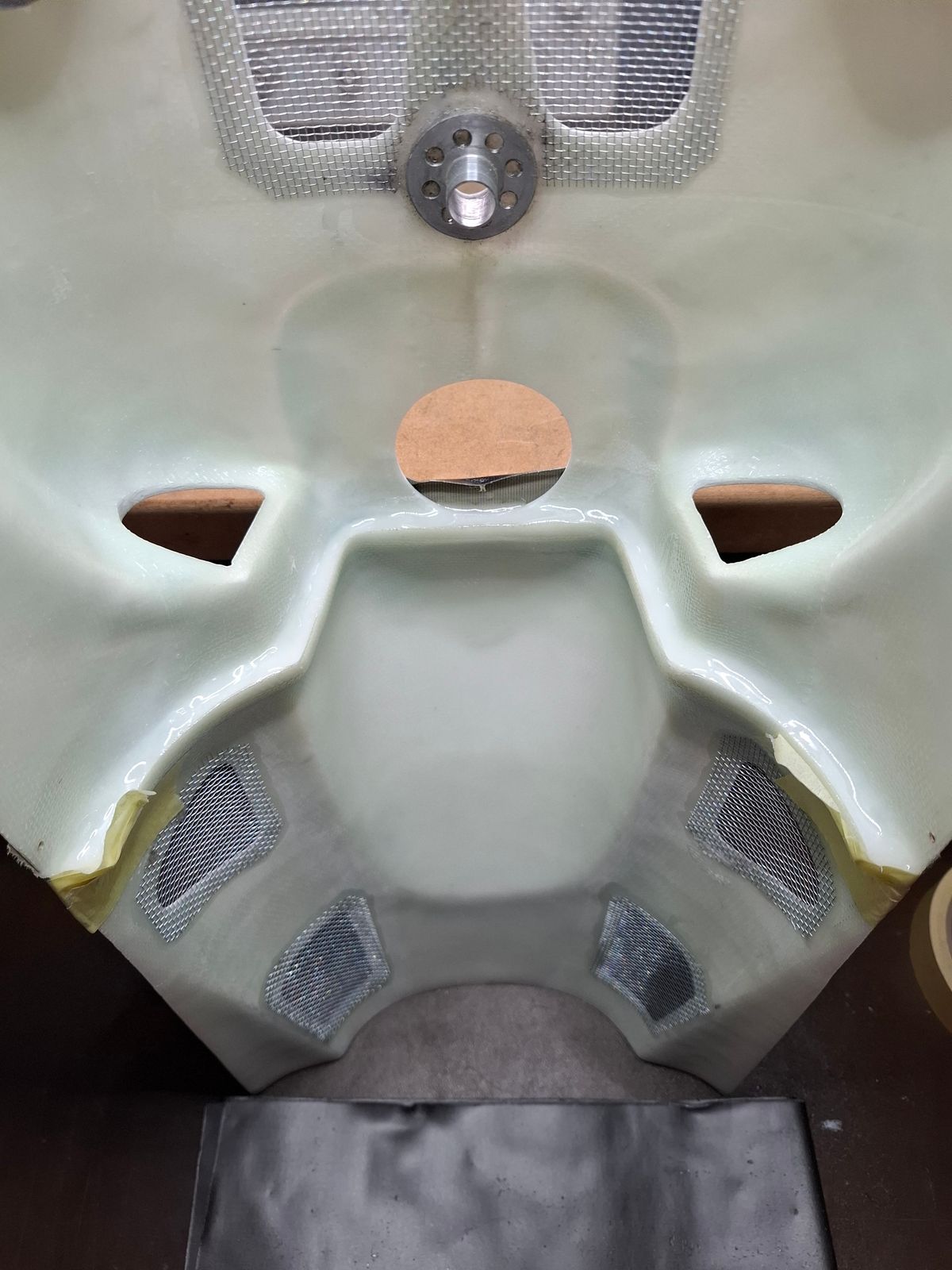
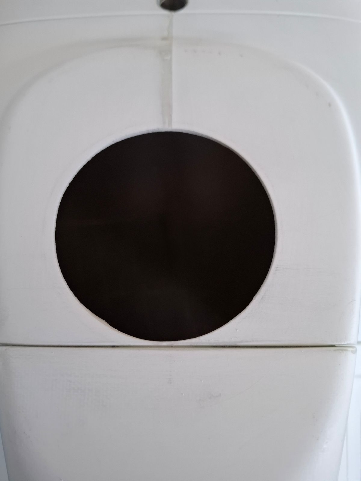
Merge the two doghouse parts into one part.
Due to the close circle edge of the head linkage hole to the doghouse parting position i had to glue the two parts together.
Epoxy mixture with Aerosil to make it a fluid paste.
25 Comments
Let the journey begin! Have fun!
Thanks, love to build those machines.
The owner must be very happy that you build his machine!
I would certainly be very happy. 😄
Beautiful work, Danny!
I like it Danny! 👍
Thanks.
Very nice
That’s gonna be a hell of a beauty!
We spare no effort to make a light weight an good flying scale model.
Nice!
Nice work Danny!
Thanks
Nice glue work!
Thanks, the costumer is very high demanding..... 😄
Looks neat and professional!
Thank you. It takes a lot of work, but a nice result is a joy forever.
Great pro work Danny !
Thanks.
Yes, topside connection is key to avoid fiddly oscillations. Without using a camera, one can only see tail movements without noticing that's coming from the head.
I also use a camera inside the cockpit to monitor vibrations and eventual degradation over time
of the components, like real airliners monitoring vibrations for certain parts (I'm using insta360 go 2).
Find real test video.
https://youtu.be/A0fADnsNXnE?si=_9wej7uAc5Sgdz_P
Very interesting video, so you can see really what is happening.
I always make a stable and sustainable connection as close to the topside of the mechanics as possible, never had issue's with vibration.
Thanks for sharing the video!
I’m enjoying the pictorial journey.
How nice is this again! Faboulous!
Danny, how will you cover the screw caps that hold the LiPo trays? It would be an issue if the battery would rub on the screw...
Hello, there will be a "L" shaped foam installed on the carbon plates so the Lipo's can not touch the screw and ALu base frame.