

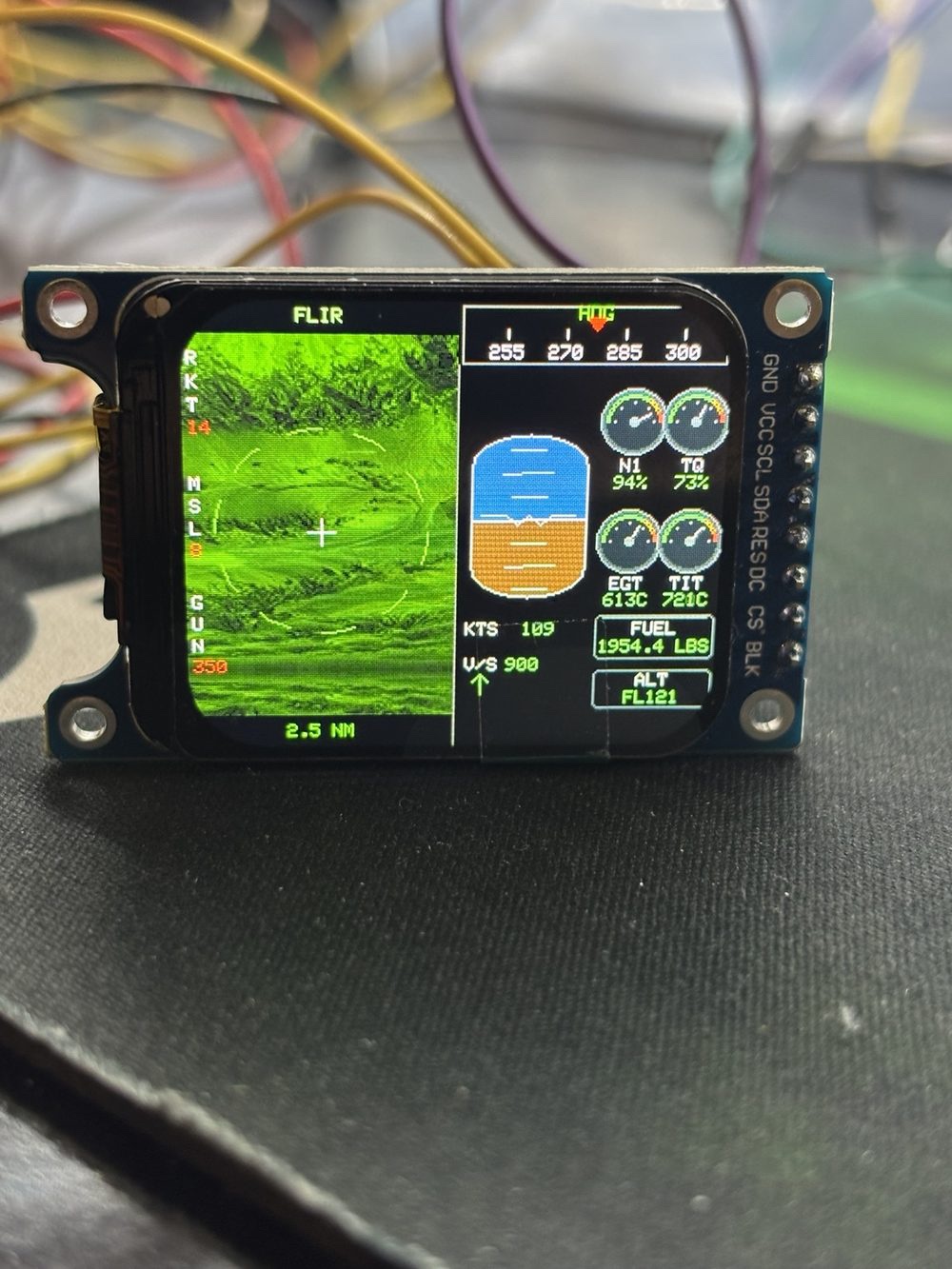
Building a Four-Page Glass Cockpit for the Roban 470 Cobra
From selecting the miniature TFT display and soldering the wiring harness to programming the ESP32, creating four cockpit pages, and adding an animated startup sequence.
BY JON | NOVEMBER 2026 | ILLUSTRATED BUILD ARTICLE
I wanted the cockpit of my Roban 470 Cobra to look like something more than a static model interior. My goal was a miniature electronic instrument display that would fit inside the helicopter, present convincing aviation-style information, and operate as its own compact system.
What began as a single-screen flight-instrument idea eventually became a four-page multifunction display (MFD), complete with a dedicated startup screen, FLIR-style moving terrain, engine and weapons indications, a radar/communications page, and a wireless control interface. The finished design uses one physical LCD that can show four different full-screen layouts.
0 1 / T H E P L A N
Choosing the Hardware
I started with the idea of using a small color TFT and an ESP32 microcontroller. An early layout was developed for a 1.3-inch, 240 × 240 ST7789 display. As the cockpit design grew, I moved to a 1.69-inch, 240 × 280 ST7789-family TFT, giving me a little more space for the instruments while keeping the module compact enough for the Cobra.
The later working hardware shown in my build photographs is labeled 1.69-inch TFT V1.4, ST7789V3, 240 RGB × 280. It is driven by an ESP32 DevKit V1. The LCD is turned sideways in software, giving a 280 × 240 landscape instrument panel.
Equipment Purpose
ESP32 DevKit V1, 30-pin board
Main microcontroller, SPI graphics, Wi-Fi control, and program storage
1.69-inch ST7789V3 TFT, 240 × 280
Single cockpit display, operated in landscape orientation
2S 450 mAh LiPo battery
Dedicated power source for the cockpit electronics
AKEYRC 5V buck converter
Reduces the 2S battery voltage to regulated 5V for the ESP32
Fine insulated hookup wire and solder Point-to-point electrical connections
Soldering iron, cutters, wire stripper, heat-shrink insulation
Building and securing the wiring harness
Digital multimeter and USB cable
Checking supply voltage and programming the ESP32
Computer running Arduino IDE Editing, compiling, and uploading the firmware
During development I also worked with an MPU-6050 motion sensor and a BMM150 magnetometer. The final simplified display hardware did not require a magnetometer, and the four-page firmware retained optional MPU-6050 support. The engine, stores, radar targets, and many flight readouts are presentation simulations, rather than telemetry from the helicopter's flight controller.
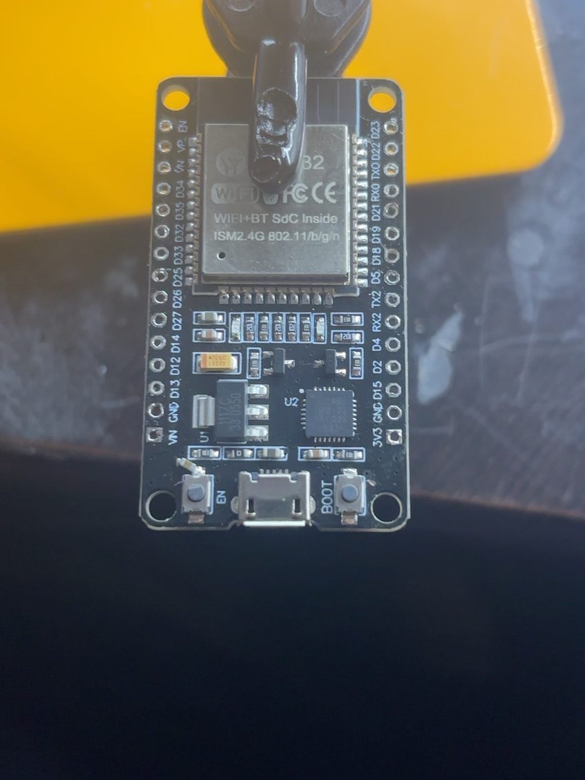
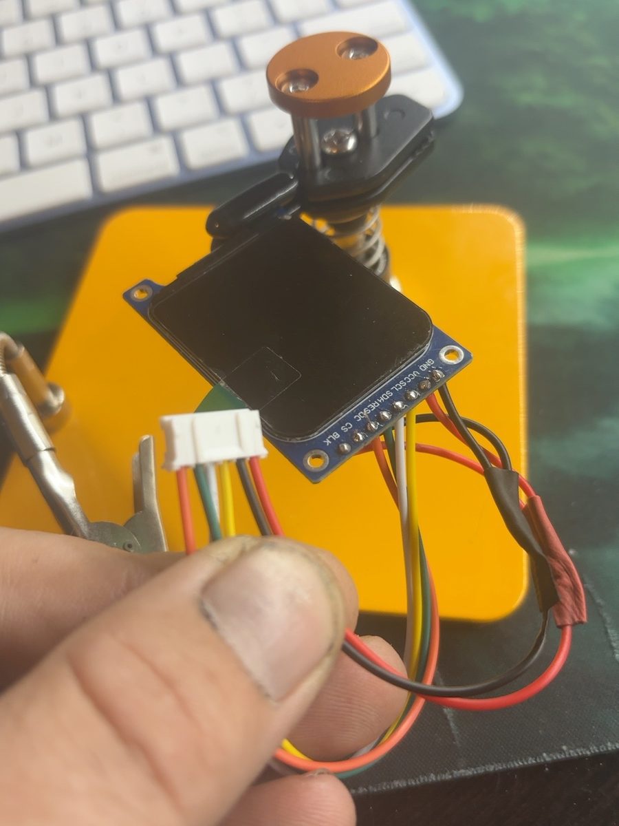
The compact display module and point-to-point wire harness during assembly.
0 2 / C O N N E C T I O N S
Connecting the ESP32 to the TFT
The display uses a four-wire SPI interface. Two ESP32 pins carry the clock and pixel data, and two more control the display's command/data selection and reset. In the working sketch, the LCD chip-select is held active, so the software does not assign a separate chip-select GPIO.
ST7789V3 display pad ESP32 connection Function
VCC 3V3 3.3V display supply
GND GND Common ground
SDA / DIN / MOSI GPIO 23 (D23)
SPI pixel data
SCL / SCK / CLK GPIO 18 (D18)
SPI clock
DC GPIO 27 (D27)
Data/command selection
RES / RST GPIO 26 (D26)
LCD reset
CS GND Chip-select permanently active
BLK / BL 3V3 Backlight enabled
Match the labels, not the physical pin position. The successful build uses the labeled ST7789V3 display shown in the photographs. Other 1.69-inch modules, including touch-equipped variants, can have different connectors and pin arrangements. The final firmware's LCD constructor uses no separate CS pin.
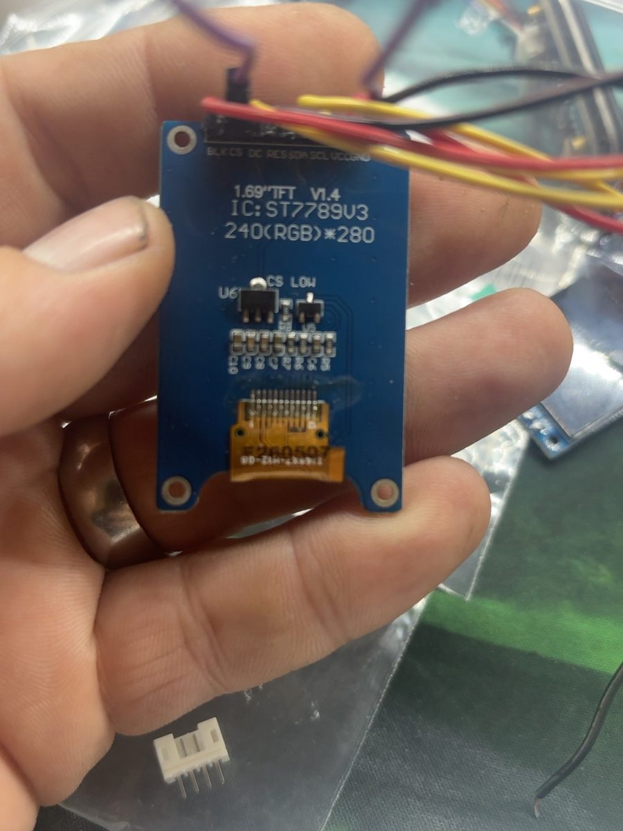
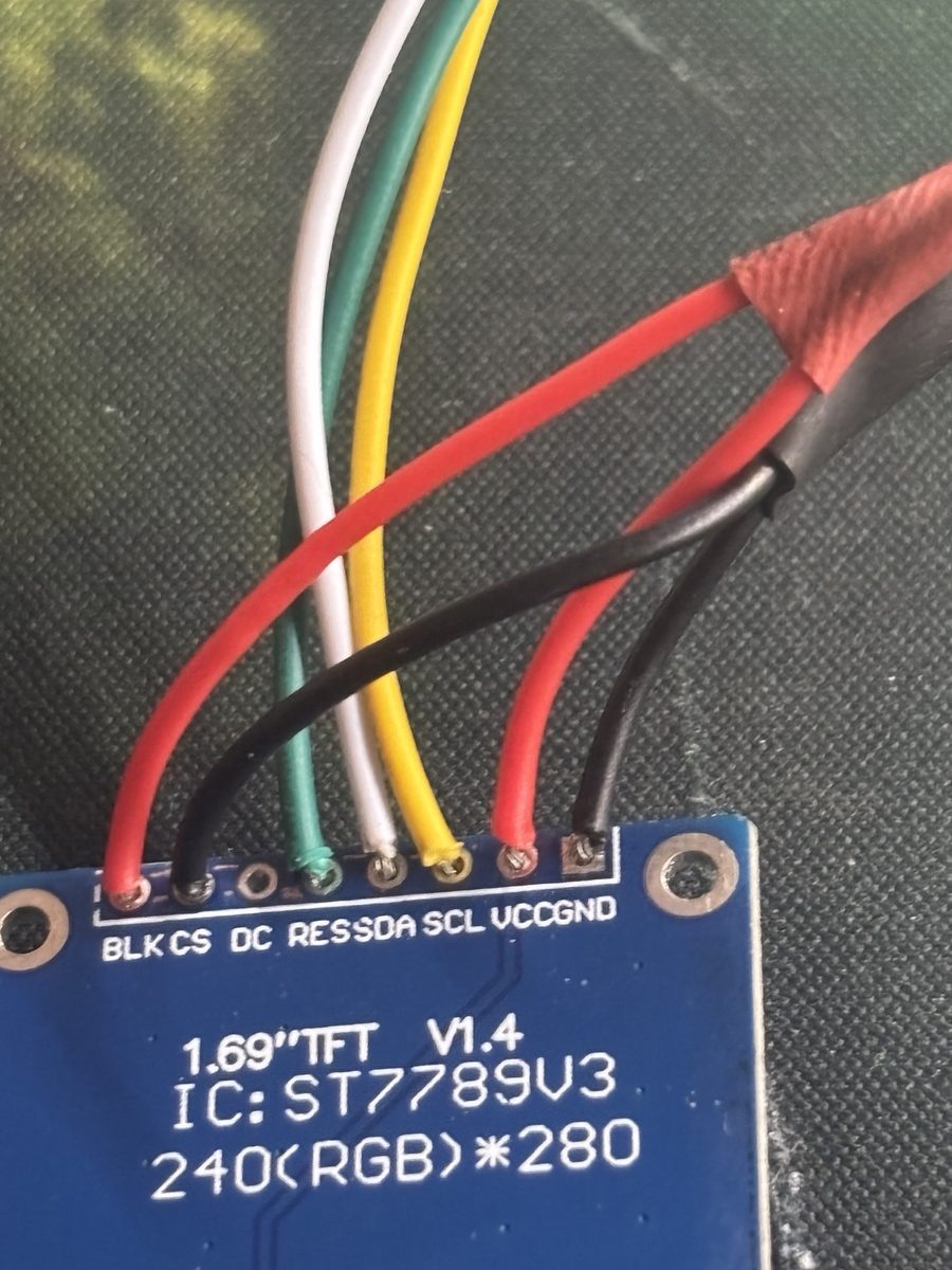
Close-up of the display’s labeled solder connections; the actual printed labels are the reference for wiring.
The touchscreen was not used for this cockpit. Page changes and settings are handled through the ESP32's own wireless control page, so no touch-controller wiring is required.
0 3 / A S S E M B LY
Making the Point-to-Point Solder Connections
Space inside the model was limited, so I built a direct-wired harness rather than using a temporary plug-in prototyping layout. The display board has small solder pads along its edge, and each wire was routed to the corresponding labeled connection on the ESP32.
Plan the harness. Position the TFT and ESP32 as they will sit in the helicopter and allow enough wire length to install or remove the assembly without pulling on the pads.
01
Prepare the wire ends. Cut fine insulated wires to length, strip a short section of insulation, and lightly tin each exposed conductor.
02
Tin the connection pads. Apply a small amount of solder to the selected TFT pad and the matching ESP32 connection, keeping adjacent pads separate.
03
Solder the signal leads. Attach DIN to D23, CLK to D18, DC to D27, and RST to D26, working from the printed labels rather than the apparent order in a drawing.
04
- Complete power and control wiring. Connect TFT VCC and BLK to the
- 3.3V rail, and connect TFT GND and CS to the common ground.
05
Finish the harness. Inspect each joint for solder bridges, protect exposed connections, and provide strain relief so vibration and handling do not load the tiny TFT pads.
The result is a compact assembly with only the wiring needed for the LCD. The screen remains a single module even though it provides several cockpit displays.
0 4 / P O W E R
Powering the Cockpit from a Separate Battery
For bench programming, the ESP32 can be powered over USB. For installation in the Cobra, I planned a separate 2S 450 mAh LiPo feeding an AKEYRC 5V buck converter. This keeps the cockpit electronics on their own supply.
2S LiPo
7.4V nominal →
5V buck converter
regulated output →
ESP32 VIN + GND →
ESP32 3V3
TFT VCC + BLK
The converter's regulated positive output connects to ESP32 VIN; the converter's negative output connects to ESP32 GND. The ESP32 then supplies the TFT's 3.3V connections. All grounds are common. The converter output is checked with a multimeter before connecting the ESP32; a 2S LiPo must not be connected directly to the TFT or the ESP32's 3V3 pin.
0 5 / P R O G R A M M I N G
Building the Software in Arduino IDE
The software was developed and uploaded using Arduino IDE, with the ESP32 board support package installed and the board selected as an ESP32 development module. The finished four-page program is preserved as Cobra_AH1W_Four_Screen_MFD_Last_Confirmed_Working(1).ino. The working sketch uses SPI.h, Adafruit GFX, and the Adafruit ST7735/ST7789 library for the display. It also includes the ESP32 WiFi, WebServer, and Preferences libraries for wireless page selection and saved settings. The optional MPU-6050 code uses Wire.h for I²C communication.
Setting in the working sketch Value
Display initialization tft.init(240, 280, SPI_MODE3)
Display rotation tft.setRotation(1) — 280 × 240 landscape
SPI clock 40 MHz in the saved working sketch
LCD driver constructor Adafruit_ST7789 tft(-1, 27, 26)
Page selection Four software pages, numbered 0–3
Startup sequence 30 seconds
Rather than storing a separate full-frame image for every moving display element, the software draws smaller bands and instrument regions into reusable graphics buffers. This keeps the visual updates manageable on the ESP32 while allowing the FLIR and radar pages to animate.
0 6 / T H E F O U R PA G E S
Turning One Screen into a Multifunction Display
The original concept combined terrain imagery and instruments on a split screen. As the graphics evolved, I settled on four individual pages, each using the full 280 × 240 display area. The following images are the approved layout previews from the project.
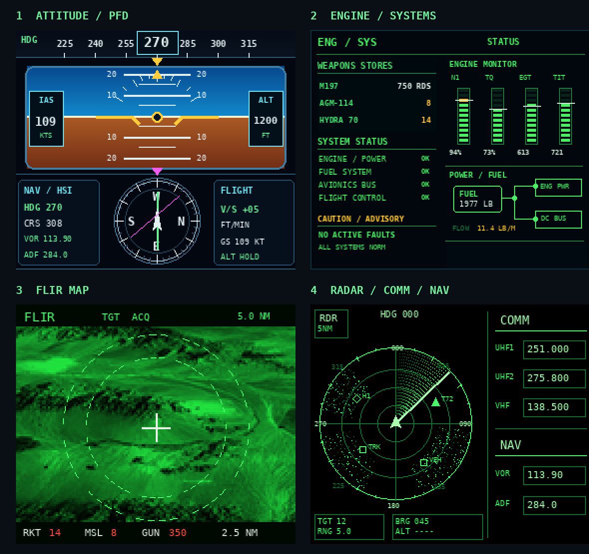
Page 1 — Attitude / Primary Flight Display
The flight page presents an artificial horizon with pitch and roll indications, a heading display, and compact speed and vertical-speed information. It gives the small Cobra cockpit a recognizable glass-panel appearance. In the saved firmware, the altitude reference is FL120, and some numerical flight values are simulated. If an MPU-6050 is fitted and recognized, the code can use it for attitude and gyro-derived heading.
Attitude/PFD layout preview.
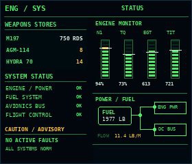
Page 2 — Engine and Systems
The engine page uses vertical instrument tapes for N1, torque, EGT, TIT, and rotor RPM, together with fuel quantity, simulated system status, and weapons-store readouts. The store labels include the M197 cannon, AGM-114 missiles, and Hydra 70 rockets. These are modeled cockpit indications, not live engine measurements.
Page 3 — FLIR Terrain Display
The FLIR page uses the green mountain/terrain image developed earlier in the project. The terrain scrolls beneath a centered sight reticle, with range and stores information overlaid. To fit the artwork on the small screen, the software draws the picture in horizontal strips rather than requiring a large full-screen image buffer.
FLIR layout preview with green terrain and centered reticle.
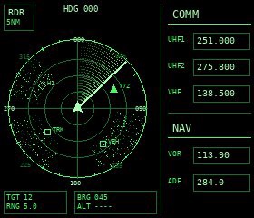
Page 4 — Radar / COMM / NAV
The fourth page combines a radar-style circular scope with a separate communications and navigation column. The radar has range rings, heading references, simulated contacts, and a single slower sweeping line. The right side shows adjustable UHF, VHF, VOR, and ADF frequency fields. The values are display simulations and do not transmit or tune a real aircraft radio.
0 7 / B O O T S E Q U E N C E
Adding the Animated Cobra Splash Screen
The last major visual addition was a dedicated startup sequence. When the ESP32 powers up, the TFT shows Cobra-themed artwork and a series of animated system checks before switching to the selected instrument page.
The saved four-page sketch runs this sequence for 30 seconds. Its diagnostic-style messages progress through red, amber, and green states, while the artwork and weapons highlights change as the sequence advances. The startup graphics are a visual simulation; the firmware separately initializes the onboard Wi-Fi service and checks for an optional MPU-6050.
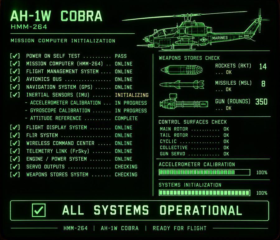
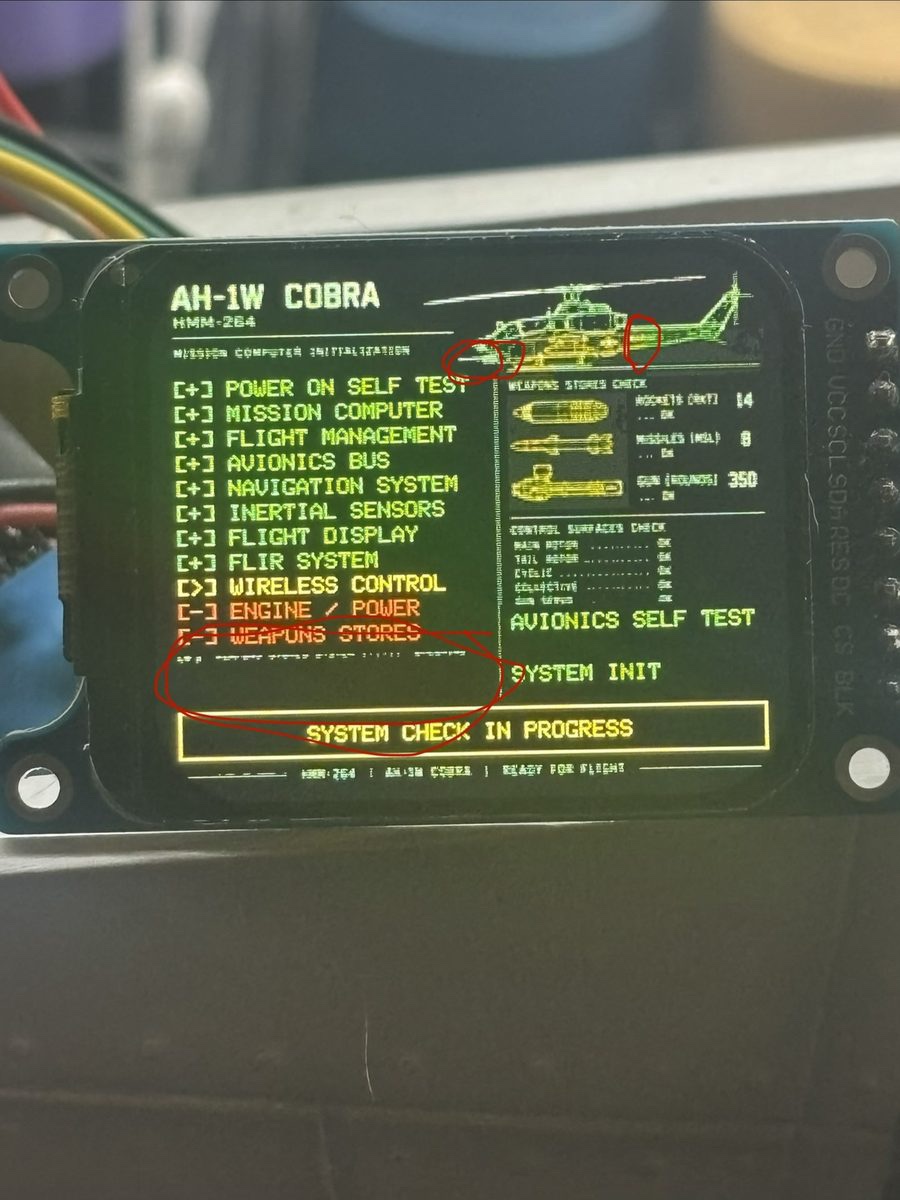
Approved full-screen startup artwork used as a visual reference for the animated boot sequence.
At the end of the sequence, the screen reports that the visual checks are complete and opens the selected cockpit page. The effect gives the miniature display the feel of a dedicated avionics unit rather than a generic LCD.
0 8 / W I R E L E S S C O N T R O L
Changing Pages without Touchscreen Wiring
The ESP32 creates its own local Wi-Fi network named Cobra-Cockpit. A phone or computer connected to that network can open the ESP32's built-in control website. An internet connection is not required for this local interface.
The control page offers four display selections — Attitude, Engine, FLIR Map, and Radar/COMM — along with simulated radio-frequency settings, FLIR scroll speed, and heading/attitude adjustments. The sketch uses the ESP32 Preferences library to retain selected settings between restarts.
This arrangement avoids adding physical page-selection switches or using the display's touchscreen. It also makes it possible to change what the cockpit screen shows while the electronics remain installed inside the helicopter.
0 9 / C O M P L E T E D P R O J E C T
The Finished Four-Screen Cockpit
The final result is a compact ESP32-powered avionics display that fits the Cobra's scale. One small TFT provides a flight-instrument page, engine and stores page, FLIR-style terrain page, and radar/communications page. The 30-second startup sequence ties the system together, and the built-in Wi-Fi interface handles page selection and settings.
The project combines ordinary hobby electronics — an ESP32, an ST7789 TFT, a regulated power supply, and hand-soldered wiring — with custom graphics and a little imagination. The display is a scale cockpit effect, not a flight-critical avionics system, but it gives the Roban 470 Cobra a distinctive and much more detailed interior.
Final configuration: one 1.69-inch landscape TFT, four selectable pages, animated Cobra startup, point-to-point soldered harness, ESP32 control, and dedicated battery/buck-converter power plan.
Roban 470 Cobra — Four-Page Glass Cockpit · By Jon · Published November 2026 · Build photographs and identified display-layout previews.